Exhaust gas purification system for an internal combustion engine

a technology of exhaust gas purification system and internal combustion engine, which is applied in the direction of electric control, machines/engines, mechanical equipment, etc., can solve the problems of chemical changes on component parts, and achieve the effect of suppressing chemical changes in component parts

Inactive Publication Date: 2012-09-27
TOYOTA JIDOSHA KK
View PDF5 Cites 43 Cited by
  • Summary
  • Abstract
  • Description
  • Claims
  • Application Information

AI Technical Summary

Benefits of technology

[0054]According to the present invention, in an exhaust gas purification system for an internal combustion engine which is provided with a low pressure EGR device, it is possible to suppress chemical changes in component parts arranged in a path of an EGR gas, while suppressing an increase in the number of component parts.

Problems solved by technology

As a result, there is a possibility that the above-mentioned condensed water and / or substances evaporated from the condensed water may cause chemical changes on component parts such as a compressor, an intercooler, and so on.

Method used


Image

  • Exhaust gas purification system for an internal combustion engine
  • Exhaust gas purification system for an internal combustion engine
  • Exhaust gas purification system for an internal combustion engine

Examples


first embodiment

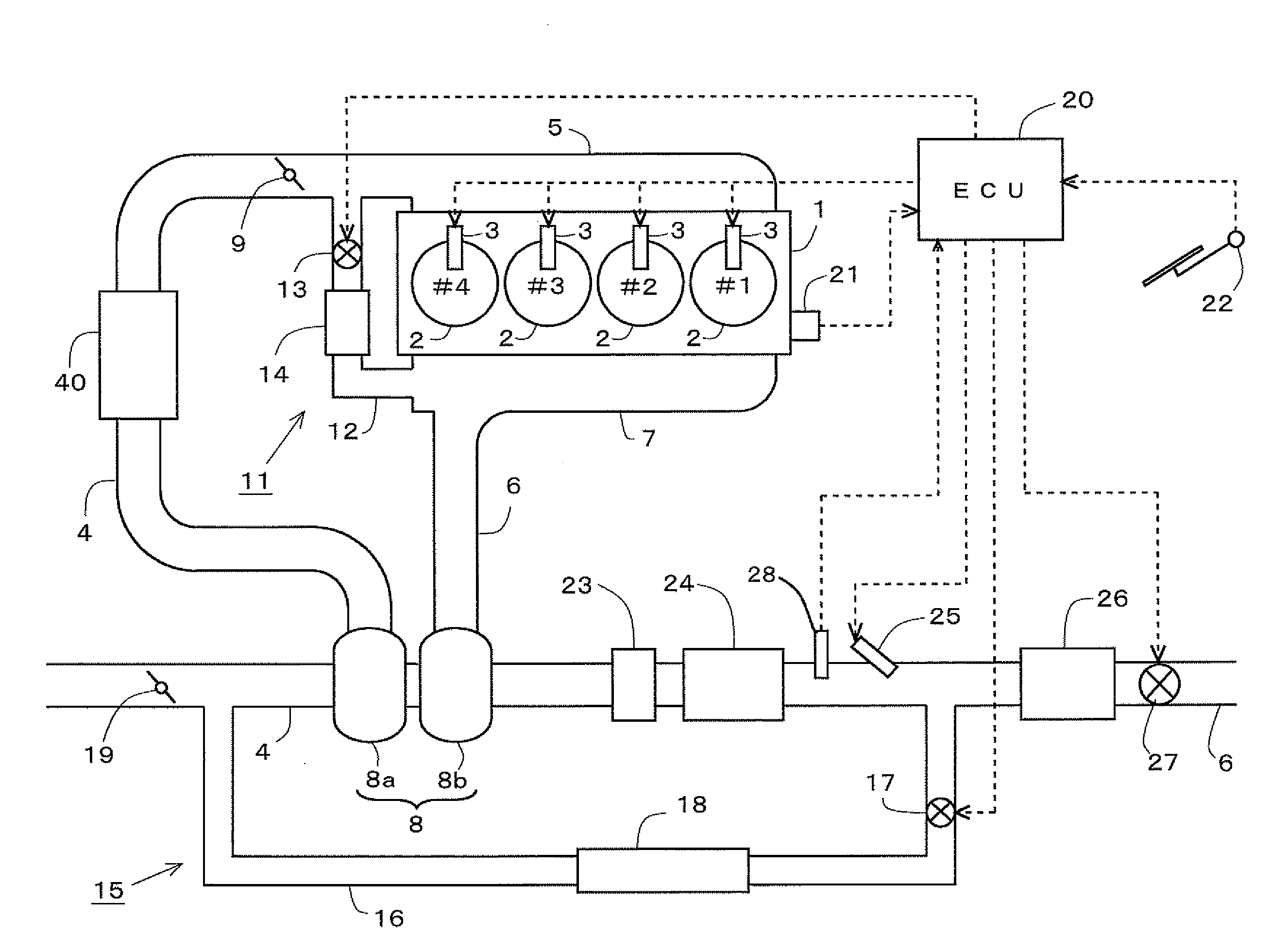
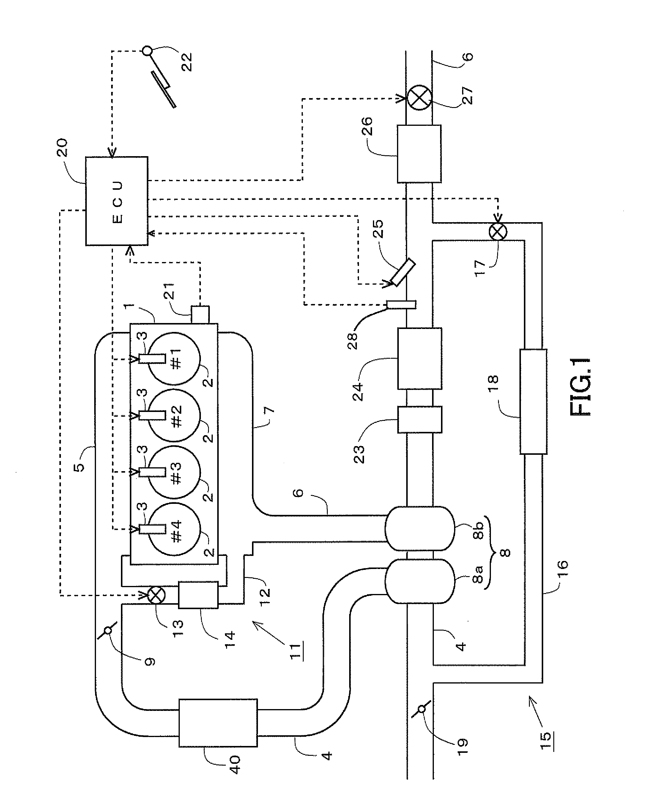
[0073]In the first place, a first embodiment of the present invention will be described with reference to FIGS. 1 and 2. FIG. 1 is a view showing the schematic construction of an exhaust gas purification system for an internal combustion engine in this first embodiment.

[0074]An internal combustion engine 1 shown in FIG. 1 is a compression ignition type internal combustion engine (diesel engine) having four cylinders 2 for use in driving a vehicle. On each of the cylinders 2 of the internal combustion engine 1, there is mounted a fuel injection valve 3 for directly injecting fuel into a corresponding cylinder 2.

[0075]An intake manifold 5 and an exhaust manifold 7 are connected to the internal combustion engine 1. An intake passage 4 is connected to the intake manifold 5. An exhaust passage 6 is connected to the exhaust manifold 7. A centrifugal supercharger (turbocharger) 8 has a compressor 8a arranged in the intake passage 4. The turbocharger 8 has a turbine 8b arranged in the exhau...

second embodiment

[0105]Next, a second embodiment of the present invention will be described with reference to FIG. 3. Here, a construction different from that of the above-mentioned first embodiment will be described, and an explanation of the same construction will be omitted.

[0106]The difference of this second embodiment from the above-mentioned first embodiment is that a dispersion plate for dispersing an urea aqueous solution supplied from the addition valve 25 is arranged in a portion of the exhaust passage 6 at the upstream side of the selective reduction type catalyst 26.

[0107]FIG. 3 is a view showing the schematic construction of an exhaust gas purification system for an internal combustion engine in this second embodiment. As shown in FIG. 3, the dispersion plate 29 is arranged in a portion of the exhaust passage 6 at the upstream side of the selective reduction type catalyst 26 and at the downstream side of the connection portion of the low pressure EGR passage 16. The other construction o...

third embodiment

[0110]Now, a third embodiment of the present invention will be described with reference to FIGS. 4 and 5. Here, a construction different from that of the above-mentioned first embodiment will be described, and an explanation of the same construction will be omitted.

[0111]The difference of this third embodiment from the above-mentioned first embodiment is that acid neutralization processing is carried out during the time when deceleration fuel cut-off control of the internal combustion engine 1 is in an execution state.

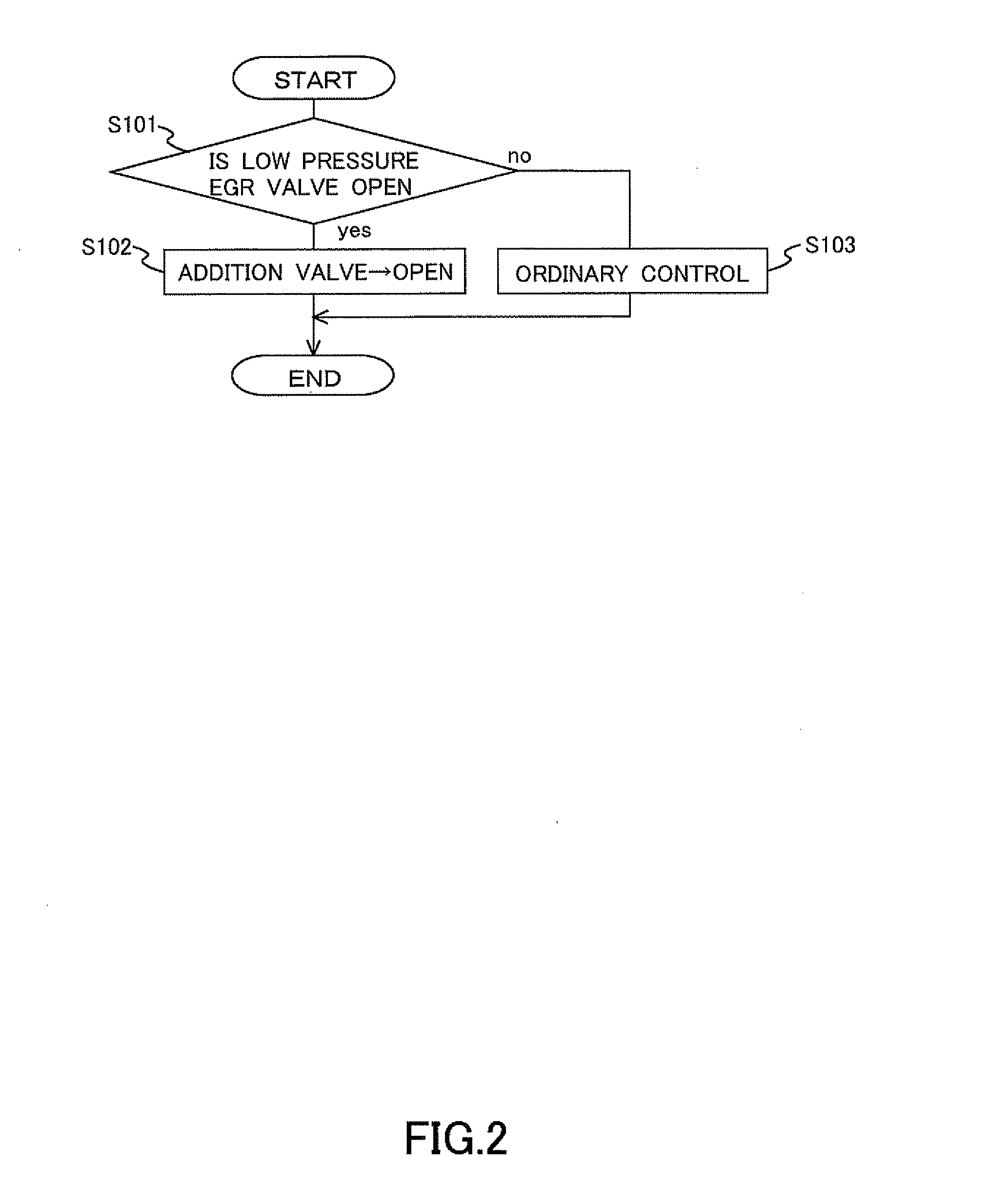
[0112]In the following, an execution procedure of the acid neutralization processing in this embodiment will be described refer to FIG. 4. FIG. 4 is a flow chart showing a control routine which the ECU 20 carries out at the time of executing the acid neutralization processing. This control routine has been beforehand stored in the ROM of the ECU 20, etc., and is carried out by the ECU 20 in a periodical manner.

[0113]In the control routine of FIG. 4, the ECU 20 determin...


PUM


Abstract

An exhaust gas purification system for an internal combustion engine, which is provided with: a selective reduction type catalyst arranged in an exhaust passage of the internal combustion engine; a low pressure EGR mechanism that is equipped with a low pressure EGR passage for introducing a part of an exhaust gas flowing through a portion of the exhaust passage downstream of a turbine of a centrifugal supercharger to a portion of an intake passage upstream of a compressor as a low pressure EGR gas, and a low pressure EGR valve for changing a channel cross section of the low pressure EGR passage; a supply device.

Description

TECHNICAL FIELD[0001]The present invention relates to an exhaust gas purification system for an internal combustion engine, and in particular to a technique which serves to suppress the component parts of an intake system from being corroded by an EGR (Exhaust Gas Recirculation) gas.BACKGROUND ART[0002]In recent years, there has been known a low pressure EGR device (LPL-EGR system) which serves to introduce a part of an exhaust gas flowing downstream of a turbine of a centrifugal supercharger into intake air upstream of a compressor thereof. In an internal combustion engine provided with an LPL-EGR system, when condensed water existing in a path of an EGR gas comes in contact with the EGR gas, the hydrogen ion exponent or power of hydrogen ions (pH) of the condensed water may be dropped (or strongly acidized or oxidized).[0003]As a result, there is a possibility that the above-mentioned condensed water and / or substances evaporated from the condensed water may cause chemical changes ...

Claims


Application Information

Patent Timeline
Patent Type & Authority Applications(United States)
IPC IPC(8): F02M25/07F01N3/24
CPCF01N3/2013F01N3/20F01N2240/36F01N2240/40F01N2610/02F01N2610/1453F02B29/0406F02B37/22F02D41/005F02D41/0065F02D41/126F02M25/0707F02M25/0709F02M25/0713F02M25/0718F02M25/0727F02M25/0742Y02T10/26Y02T10/47Y02T10/24F01N13/009F01N3/208F02M26/05F02M26/06F02M26/10F02M26/15F02M26/23F02M26/36Y02T10/12Y02T10/40F02M26/08
Inventor KAWAGUCHI, BUNGOODA, TOMIHISAONISHI, TOMOMISATO, MASAAKIKOBAYAKAWA, SATOSHISHIRASAWA, TAKERU
Owner TOYOTA JIDOSHA KK
Why Eureka
Try Eureka