
Electroless Plated Fluid Flow Conditioner and Pipe Assembly

a technology of fluid flow conditioner and electroless plating, which is applied in the direction of liquid/solution decomposition chemical coating, volume/mass flow by differential pressure, corrosion prevention, etc., can solve the problem of long straight pipe length, inability to measure fluid flow rate consistently accurate and repeatable, and inability to meet the requirements of continuous measurement. the effect of fluid flow rate, avoiding errors, and preventing material buildup

Inactive Publication Date: 2012-10-04
CANADA PIPELINE ACCESSORIES
View PDF10 Cites 29 Cited by
  • Summary
  • Abstract
  • Description
  • Claims
  • Application Information

AI Technical Summary

Benefits of technology

[0021]An advantage of the present invention is the prevention of material buildup on the surface of flow conditioners and piping components.
[0022]Another advantage of the present invention is improving the accuracy of fluid flow measurement systems by avoiding errors due to distorted flow caused by contaminant buildup.
[0023]Another advantage of the present invention is avoiding the necessity to frequently clean or replace fluid flow measurement components, including flow conditioners, flow meters, and sections of pipe, due to diminished meter accuracy or repeatability caused by contaminant buildup.
[0024]As used herein “substantially”, “relatively”, “generally”, “about”, and “approximately” are relative modifiers intended to indicate permissible variation from the characteristic so modified. They are not intended to be limited to the absolute value or characteristic which it modifies but rather approaching or approximating such a physical or functional characteristic.
[0025]In the detailed description, references to “one embodiment”, “an embodiment”, or “in embodiments” mean that the feature being referred to is included in at least one embodiment of the invention. Moreover, separate references to “one embodiment”, “an embodiment”, or “in embodiments” do not necessarily refer to the same embodiment; however, neither are such embodiments mutually exclusive, unless so stated, and except as will be readily apparent to those skilled in the art. Thus, the invention can include any variety of combinations and / or integrations of the embodiments described herein.IV.

Problems solved by technology

However, having long lengths of straight pipe is impractical and cost prohibitive.
As a result, meter station piping often contains elbows, tees, valves and other assemblies that distort the flow profile into an asymmetric, unstable, and distorted configuration.
This makes it very difficult to measure the fluid flow rate in a consistently accurate and repeatable manner.
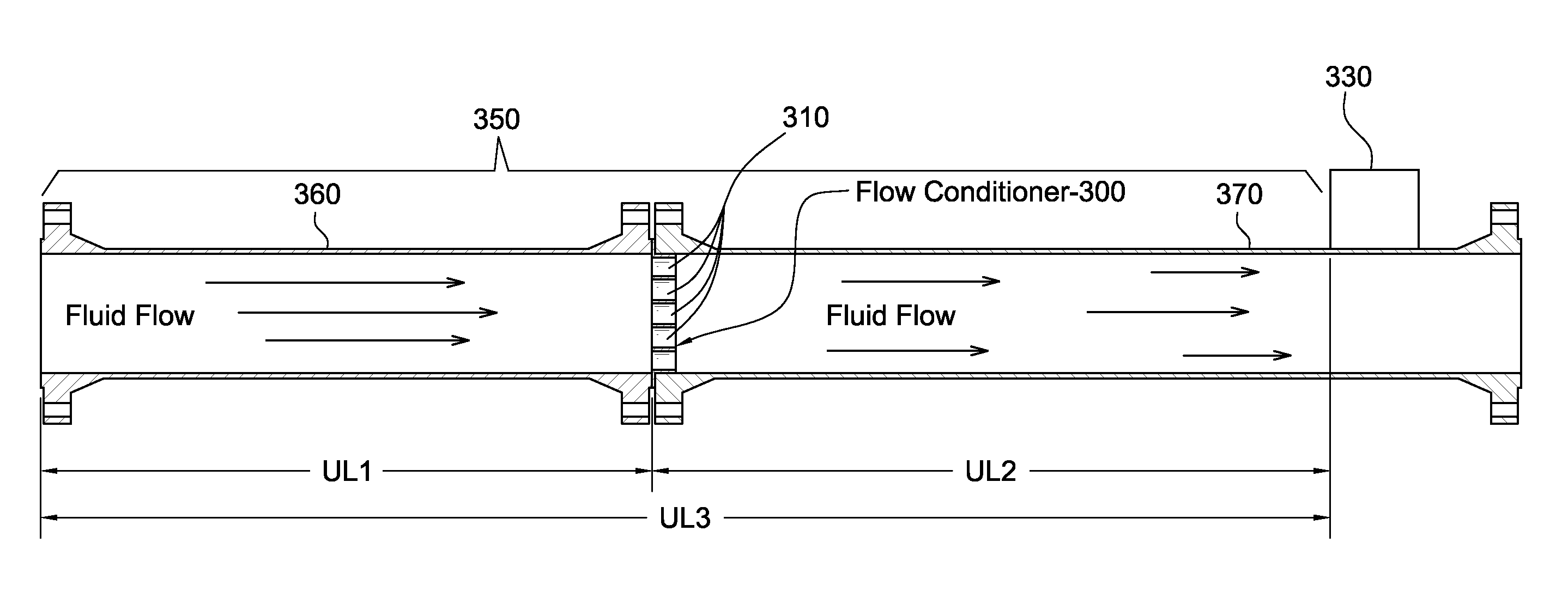
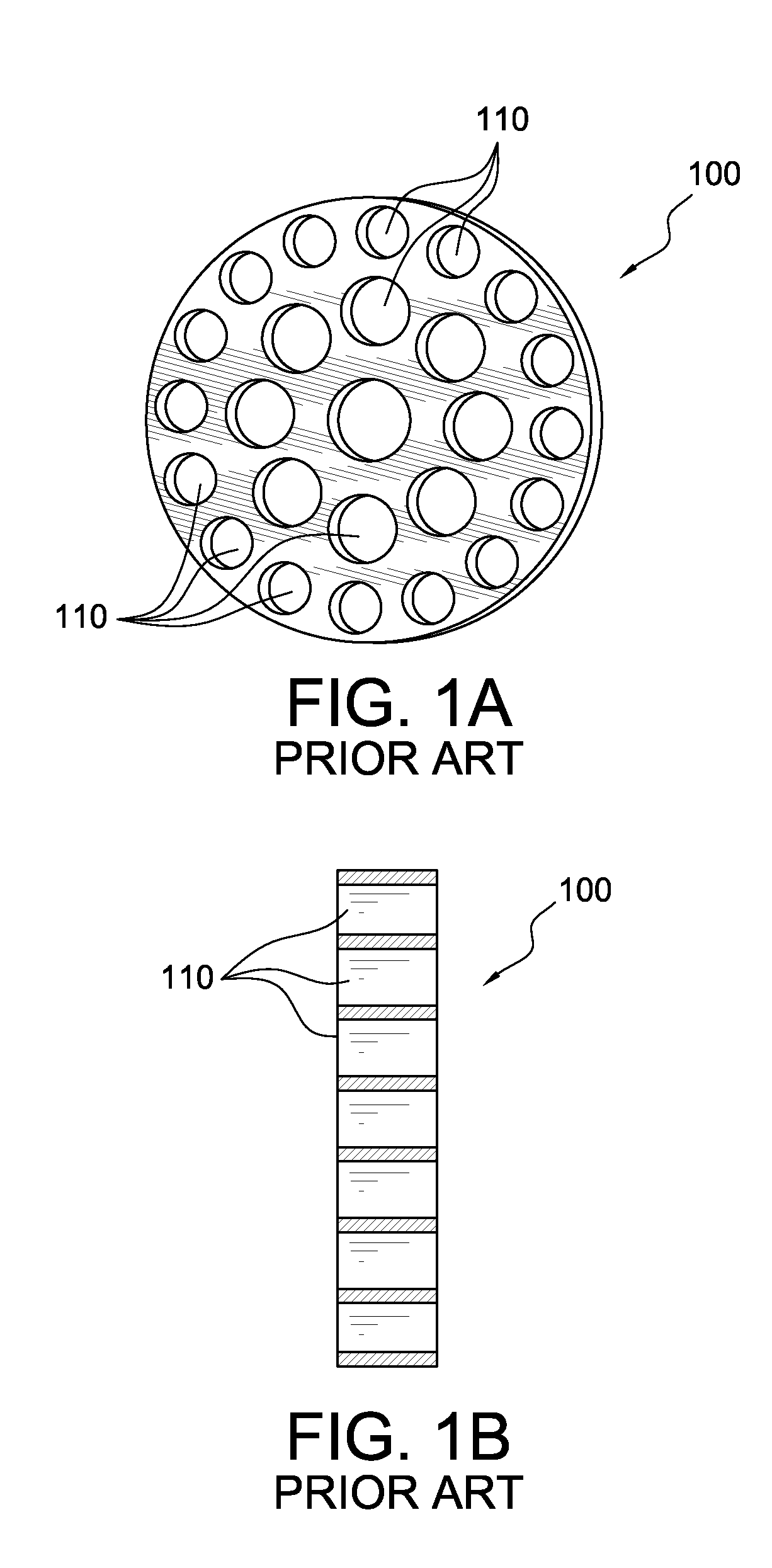
Flow conditioners are effective in eliminating bulk rotation and correcting asymmetric flow profiles that can lead to inaccurate flow meter readings.
However, other sources of inaccuracy can exist within typical fluid flow pipes including those with flow conditioners installed.
Fluid flow measurement systems have been found to exhibit appreciable degradation in system accuracy over time.
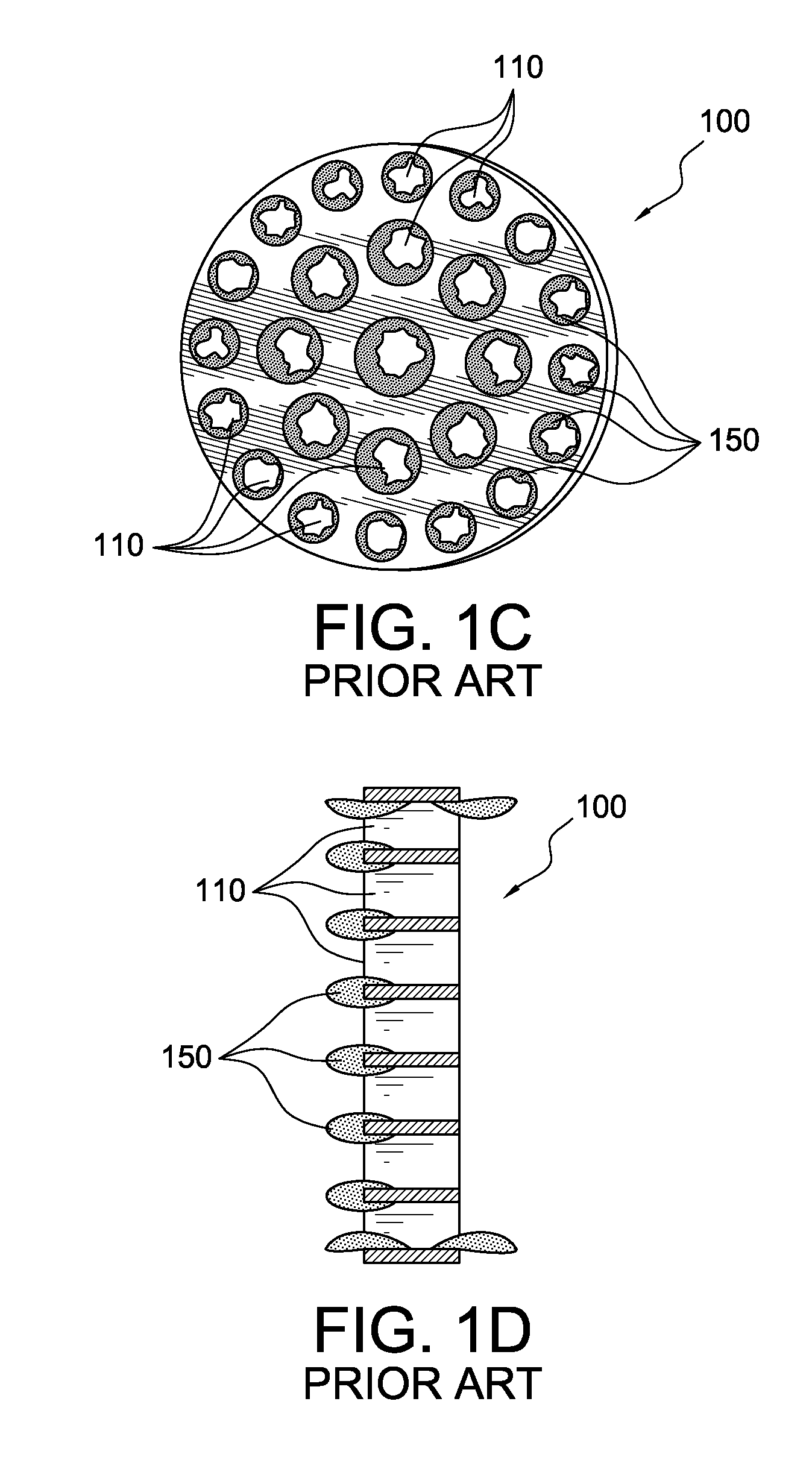
This degradation in system accuracy is usually attributed to be a result of the buildup of deposits from the fluid onto the flow conditioner, pipe, meter, and other system components.
Deposits on the surface of pipe components can alter the geometry of the components, thus changing the flow profile, and contributing to meter error.
This exposes the piping and its components to significant corrosion (chemical reactions between the fluid and the pipe component).
Due to the corrosion, typical carbon steel piping components tend to decay, i.e., rust, collect build up, flake, and / or peel—which changes the internal geometry and surface properties of the pipe, resulting in significant flow meter error.
These contaminants can erode (physically wear down over time) surfaces in a pipeline or cause physical damage through impacts, resulting in changes to the fluid pipe wall friction and significant distortions in the velocity flow profile.
Particularly, the section of pipe upstream of the flow meter is critical to system accuracy and therefore, requires frequent cleaning.
Maintenance and repair of pipelines is extremely costly and labor intensive.
Often pipelines are located in remote and austere environments that are difficult to access.

Method used


Image

  • Electroless Plated Fluid Flow Conditioner and Pipe Assembly
  • Electroless Plated Fluid Flow Conditioner and Pipe Assembly
  • Electroless Plated Fluid Flow Conditioner and Pipe Assembly

Examples


Embodiment Construction

[0036]The present invention provides an electroless nickel (EN) plated fluid flow measurement system including an electroless nickel plated fluid flow conditioner. The electroless nickel plated fluid flow measurement system may also include one or more sections of electroless nickel plated pipe wherein the fluid flow conditioner is disposed within the one or more sections of pipe. Nickel based plating is applied to the fluid flow conditioner by an electroless plating process. The electroless nickel plating enhances the corrosion and wear resistance of the flow conditioner, thereby reducing deposit buildup on the flow conditioner, which improves the accuracy and performance of the flow measurement system.

[0037]The present invention provides several advantages over known fluid flow measurement systems. These advantages include improved corrosion resistance, increased contaminant repulsion, increased surface hardness, increased surface smoothness, improved plating uniformity, and impro...


PUM

PropertyMeasurementUnit
Thicknessaaaaaaaaaa
Thicknessaaaaaaaaaa
Weightaaaaaaaaaa

Abstract

A method and system for electroless nickel plating of fluid flow measurement components used in oil and gas pipelines provides uniformly and consistently plating of all surfaces of the fluid flow components, including flow conditioners, with an electroless nickel plating that imparts the component with desirable characteristics related to hardness, smoothness, wear and abrasion resistance, and corrosion and oxidation resistance, such that the build up of contaminant deposits on the component is reduced and repeatable and accurately fluid flow measurements can be made.

Description

[0001]The U.S. nonprovisional application claims priority of provisional application No. 61 / 469,212 filed on Mar. 30, 2011 in the U.S. Patent and Trademark Office, the entirety of which is incorporated by reference herein.I. FIELD OF THE INVENTION[0002]The present invention relates to fluid flow measurement components used in oil and gas pipelines. More particularly, the present invention relates to a system and method for uniformly and consistently coating a fluid flow conditioner with an electroless nickel plating that reduces the build up of deposits on the flow conditioner.II. BACKGROUND OF THE INVENTION[0003]Pipelines are used to transport fluids in various industries, including chemical, oil and gas, and manufacturing. These industries use processes that require fluid flow rates to be accurately measured. These measurements are performed at locations known as meter stations using a variety of different meter types. These meters function in different ways, they can use: differe...

Claims


Application Information

Patent Timeline
IPC IPC(8): G01F1/00B05D3/02G01F1/42
CPCG01F1/42G01F15/00F16L55/02718C23C18/36F16L58/08C23C18/1616
Inventor SAWCHUK, DANIEL A.SAWCHUK, BLAINE D.SAWCHUK, DALE P.SELIRIO, REGINALD
Owner CANADA PIPELINE ACCESSORIES
Learn More