

Ion Detecting Device
- Summary
- Abstract
- Description
- Claims
- Application Information
AI Technical Summary
Benefits of technology
Problems solved by technology
Method used
Image

Examples
first embodiment
[0049]An ion detecting portion is allowed to operate under atmospheric pressure, and not only the force by an electric field but also the action of the air resistance, buoyant force, and the force of gravitation that are characteristic when being operated under atmospheric pressure is used as the force acting on ions, so that the following embodiment provides an example of an analyzing method in which ions are separated by a method different from a conventional technique.
[0050]Further, in order to provide a analyzing method in which the force by an electric field and the action by the force of gravitation for ions are effectively used, it is also effective to separate ions by applying the force by an electric field in a direction different from the force of gravitation (for example, the direction of the force of gravitation is different from the force by an electric field by 90 degrees). Furthermore, in the case of detecting ions by operating under atmospheric pressure, plural detec...
second embodiment
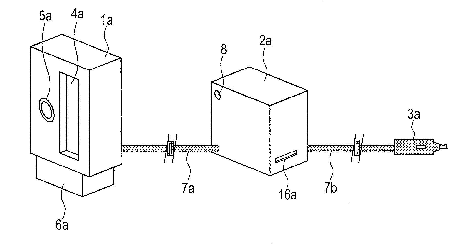
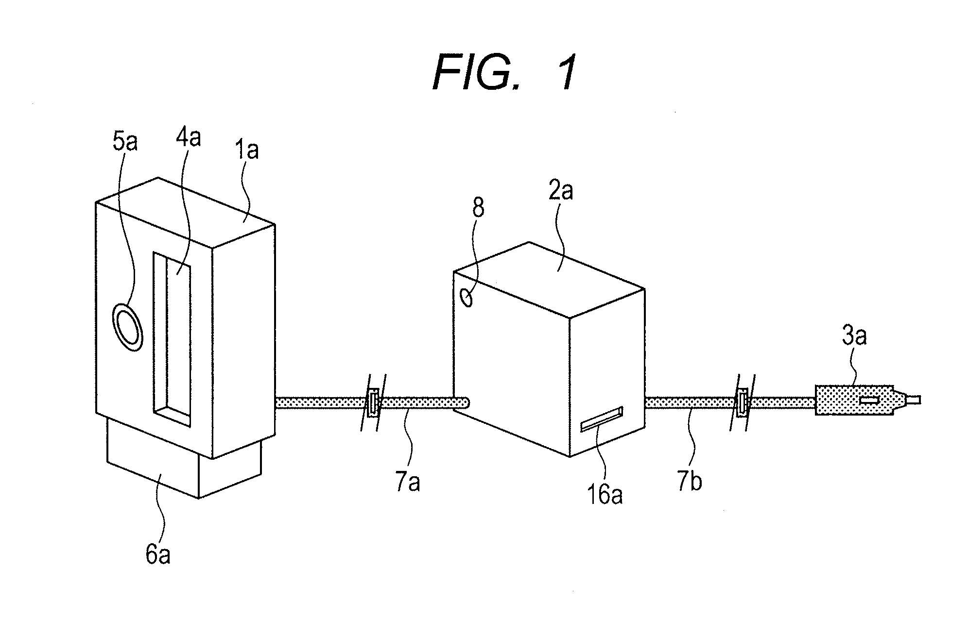
[0082]The present invention can be used for a breath alcohol sensor in a mobile object such as an automobile. If the alcohol sensor head 5a such as a semiconductor sensor is used, the sensor unit 1a and the alcohol sensor unit can be easily integrated as shown in FIG. 1. In addition, breath and alcohol can be simultaneously measured. In the case where the device is mounted in an automobile or the like, the measurement can be conducted by breathing into the device fixed on the column cover placed behind the steering wheel or by breathing into the sensor unit that is removable.
[0083]An algorithm of a breathalyzer test in the case where the present invention is used is shown in FIG. 12. For example, after starting the engine, a driver immediately breathes out into the sensor unit 1a for a few seconds in accordance with the voice guidance. Threshold values of the intensity and duration for detection of breath peaks are provided. When not exceeding the values, the driver breathes again. ...
third embodiment
[0086]As shown in FIG. 18, if only a breath inlet 28 is provided at a head set 27 and the measurement of breathing can be conducted with a head set sensor unit 30a through a transfer tube 29, the application range can be further widened. FIG. 19A shows a structure of a head set sensor unit 30b. Breath introduced from the breath inlet 28 provided at the head set 27 passes through the transfer tube 29 and is fed to a sample introduction pipe 32a through a transfer tube connector 31a as shown in FIG. 19B. A tip end of the sample introduction pipe 32a is placed at an upper portion of a sample inlet 4e of a sensor unit 1e from which breath is introduced to the sensor unit for detection. As shown in FIG. 20B, in order not to be affected by ambient air, or in order for breath to easily reach the sensor unit with an air fan (or a diaphragm pump) even if the transfer tube with a small inner diameter is used, a sample inlet of a sensor unit 1f can be completely covered with a tip end of a sam...
PUM
 Abstract
Description
Claims
Application Information