

Polymer blend composition and tunable actuators using the same
a technology of polymer blend and tunable actuator, which is applied in the direction of piezoelectric/electrostrictive transducers, device material selection, transducer types, etc., can solve the problems of disadvantage, high brittleness, and relatively high fabrication cost of piezoelectric ceramic materials, and achieve excellent miscibility
- Summary
- Abstract
- Description
- Claims
- Application Information
AI Technical Summary
Benefits of technology
Problems solved by technology
Method used
Image

Examples
synthesis example 1
Preparation of PMMA-b-PDMA-b-PMMA Block Copolymer
[0096]PDMA was prepared using dodecyl methacrylate by a typical method, and PDMA was used as a macroinitiator, together with PMMA, so as to prepare a PMMA-b-PDMA-b-PMMA block copolymer by two-step ATRP (atom transfer radical polymerization) for the preparation of an A-B-A type block copolymer.
[0097]In this connection, the hard segment PMMA block was used in an amount of 20 wt %, based on the total weight of the block copolymer, so as to give suitable ductility and physical properties
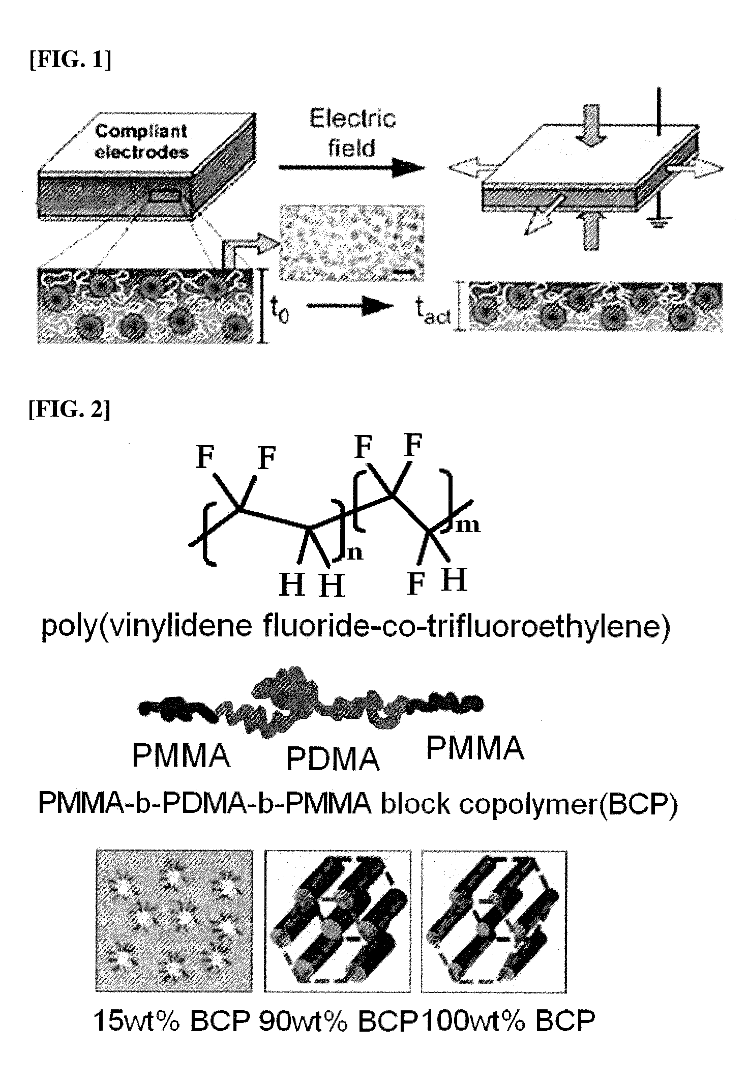
[0098]The prepared PMMA-b-PDMA-b-PMMA block copolymer had a weight average molecular weight (Mw) of 144,000 g / mol, and its molecular structure is shown in FIG. 2.
[0099]Further, the block copolymer had a tensile modulus of approximately 8 kPa (ASTM D-882, gage length: 25 mm, w: 4 mm, t: approximately 250 μm) and a dielectric constant of approximately 5.5 (10 kHz, 25° C.).
synthesis example 2
Preparation of PMMA-b-PB block copolymer
[0100]First, anionic polymerization was performed using a sec-butyllithium initiator in a toluene solvent at 30° C. for 12 hrs to polymerize polybutadiene block. Then, diphenylethylene was added thereto, and reacted with butadiene leaving ions to substitute with diphenylethylene anions, followed by reaction with methylmethacrylate at −78° C. Finally, a poly(methylmethacrylate)-b-butadiene block copolymer of Chemical Formula 1-1 was prepared. Approximately 25 wt % of poly(methylmethacrylate) was included in the prepared PMMA-b-PB block copolymer. The prepared PMMA-b-PB had a weight average molecular weight (Mw) of 52,000 g / mol.
[0101]Further, the block copolymer had a tensile modulus of approximately 40 kPa (ASTM D-882, gage length: 25 mm, w: 4 mm, t: approximately 250 μm) and a dielectric constant of approximately 4.0 (10 kHz, 25° C.).
[0102](wherein n is the same as defined the above)
example 1
PVDF / PMMA-b-PDMA-b-PMMA=85 / 15
[0103]Based on the total weight of the matrix, 85% by weight of poly(vinylidene fluoride-co-trifluoroethylene [product name: VF2-TrFe copolymer(65 / 35 w % VDF-TRFE)] purchased from Solvay solexis, Inc. and 15% by weight of the PMMA-b-PDMA-b-PMMA block copolymer (20% PMMA content) of Synthesis Example 1 were mixed with each other, and the two polymers were dissolved well in a solvent (tetrahydrofuran) under stirring for one day, so as to prepare a blend solution.
[0104]Subsequently, in order to prepare a matrix in a film type, a predetermined amount of the blend solution was put in a petri dish and slowly dried under the used solvent environment, so as to prepare a film with a thickness of 100˜200 micrometers. The film was cut to have a length and width of 20 mm, and both surfaces thereof were painted with carbon grease in a 10 mm diameter circle, so as to fabricate an actuator film.
[0105]The fabricated film was used as a dielectric layer to form top and bo...
PUM
| Property | Measurement | Unit |
|---|---|---|
| glass transition temperature | aaaaa | aaaaa |
| glass transition temperature | aaaaa | aaaaa |
| frequency | aaaaa | aaaaa |
Abstract
Description
Claims
Application Information