Switching power supply device

a power supply device and switching technology, applied in the direction of electric variable regulation, process and machine control, instruments, etc., can solve the problems of large and achieve the effect of reducing the amount of generated heat, effectively absorbing, and reducing the power loss of the switching power supply devi

Inactive Publication Date: 2012-10-04
DENSO CORP
View PDF3 Cites 65 Cited by
  • Summary
  • Abstract
  • Description
  • Claims
  • Application Information

AI Technical Summary

Benefits of technology

[0024]In this case, the amount of generated heat is reduced when the discharging current flows through the switching power supply device, compared to the case where a resistor is used as the impedance for discharging electric charges. Thus, power loss of the switching power supply device is easily reduced.
[0025]In the exemplary embodiment, the switching elements may be controlled to be driven in such a manner that an on state where the secondary coil outputs a secondary voltage repeatedly alternates with an off state where the secondary coil does not output the secondary voltage, and the snubber capacitor may have capacitance which is set so that voltage across the snubber capacitor is not reduced to zero volts in the off state.
[0026]Thus, the snubber capacitor in this case has so large a capacitance that will not allow the voltage across the snubber capacitor to be reduced to 0 V (zero volts) in the off state. Thus, surge current of the secondary coil is more effectively absorbed.

Problems solved by technology

Being not provided with such a resistor or the like, such a switching power supply device of conventional art has suffered from a problem that a high discharging current Id flows through the path.
However, an excessively large capacitance permits the charging current and the discharging current Id to be large, leading to a problem of large power loss of the switching power supply device 91.
Thus, the snubber capacitor in this case has so large a capacitance that will not allow the voltage across the snubber capacitor to be reduced to 0 V (zero volts) in the off state.

Method used


Image

  • Switching power supply device
  • Switching power supply device
  • Switching power supply device

Examples


first embodiment

[0058]Referring, first, to FIGS. 1 to 17, hereinafter is described a switching power supply device 1 according to a first embodiment of the present invention.

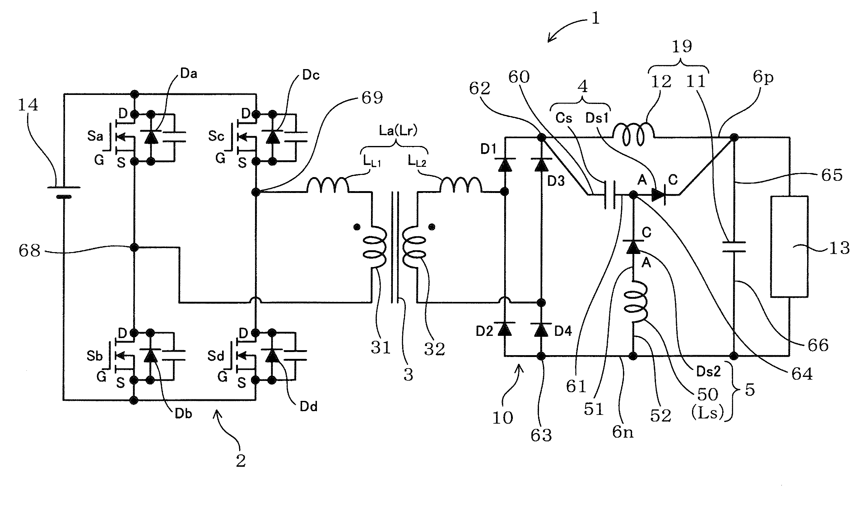
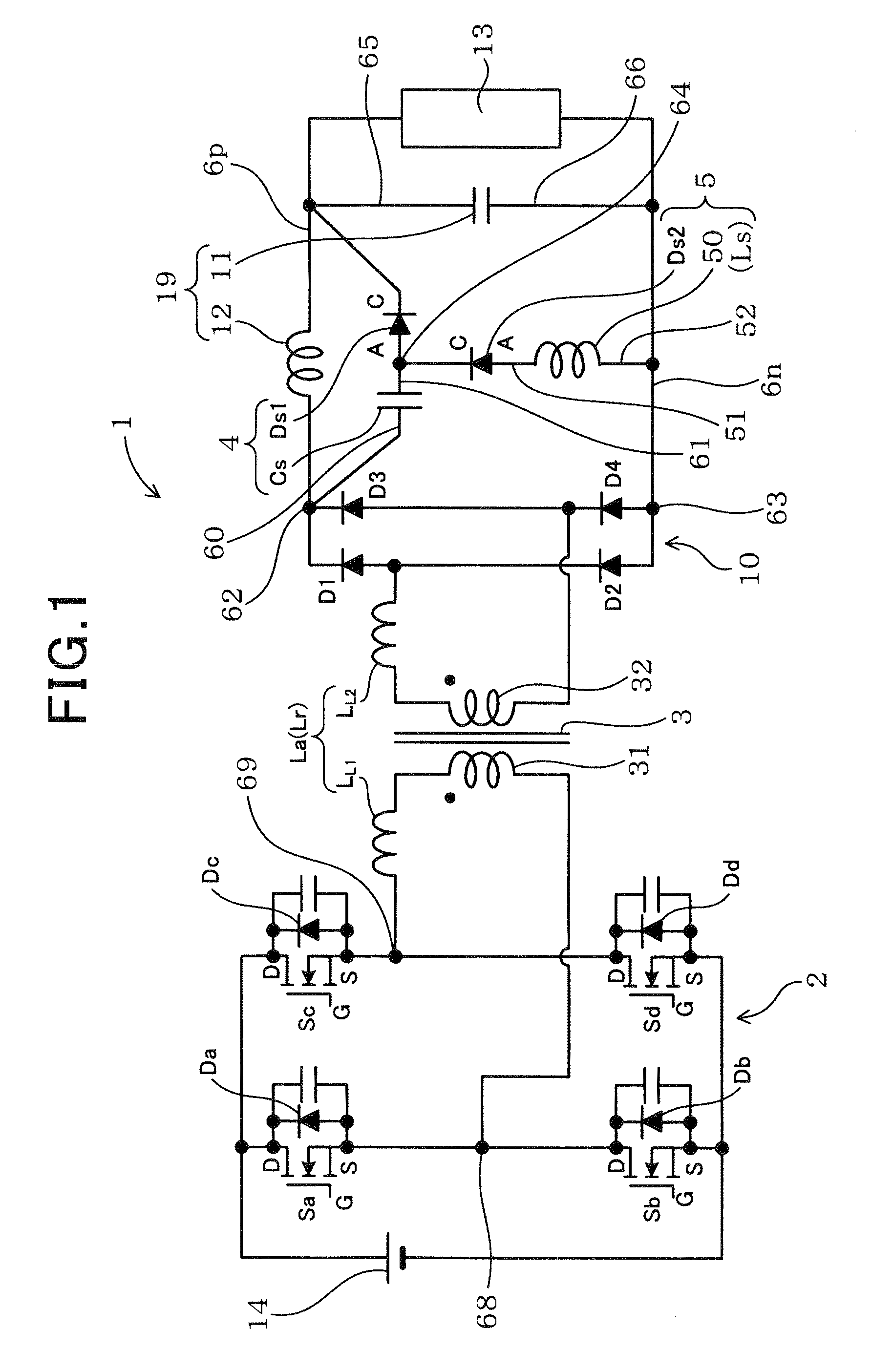
[0059]As shown in FIG. 1, the switching power supply device 1 according to the first embodiment, which is connected between a load 13 and a power source 14, includes a full-bridge circuit 2, a transformer 3, a rectifier circuit 10, a smoothing capacitor 11, a smoothing reactor 12, and a first series connection 4. The smoothing reactor 12 and the smoothing capacitor 11 configures a filter circuit 19.

[0060]The full-bridge circuit 2 includes a plurality of switching elements S (Sa to Sd). The transformer 3 includes a primary coil 31 and a secondary coil 32. The full-bridge circuit 2 has an output terminal which is connected to the primary coil 31. The rectifier circuit 10, which has an output terminal 62 on the positive side and an output terminal 63 on the negative side, is connected to the secondary coil 32 of the transformer 3 ...

second embodiment

[0109]Referring now to FIG. 20, a second embodiment of the present invention is described. In the second and the subsequent embodiments as well as in the experiments set forth below, the components identical with or similar to those in the first embodiment are given the same reference numerals for the sake of omitting unnecessary explanation.

[0110]FIG. 20 is a circuit diagram illustrating a switching power supply device 1 according to the second embodiment. As shown in FIG. 20, the switching power supply device 1 of the present embodiment is not provided with the snubber inductance Ls (the impedance 50 for discharging electric charges) but, instead, the anode of the second diode Ds2 is connected to the negative-side power line 6n.

[0111]With this configuration, the path through which the discharging current Id of the snubber capacitor Cs flows includes only the total leakage inductance La. Accordingly, the effect of suppressing the discharging current Id is small compared to the swi...

third embodiment

[0114]Referring to FIG. 21, a third embodiment of the present invention is described. FIG. 21 is a circuit diagram illustrating a switching power supply device 1 according to the third embodiment. As shown in FIG. 21, the switching power supply device 1 is used as a battery charger 100 in the present embodiment. The battery charger 100 is used for charging a battery (load 13) installed in an electric car, a hybrid car or the like, from a domestic commercial power source (power source 14).

[0115]The battery charger 100 includes a rectifier circuit 150 connected to the power source 14, a PFC (power factor correction) circuit 600 and the switching power supply device 1. The PFC circuit 600 includes a choke coil 60, an IGBT (insulated gate bipolar transistor) element 62, a diode 61 for preventing discharging, and a smoothing capacitor 63 for PFC. The battery charger 100 carries out on / off control of the IGBT element 62 to correct a reactor current IL1 flowing through the choke coil 60 to...


PUM


Abstract

A switching power supply device includes a full-bridge circuit, a transformer, a rectifier circuit, a filter circuit, a first series connection of a snubber capacitor and a first diode, and a second diode. The full-bridge circuit includes switching elements which are controlled to be driven under phase-shift control. The first series connection is connected in parallel with the smoothing reactor, where one terminal is connected to a terminal on positive side of the rectifier circuit, and the other terminal is connected to an anode of the first diode. A cathode of the first diode is connected to one terminal of the smoothing capacitor which is applied with positive voltage. The second diode is provided between a terminal on negative side of the rectifier circuit and a connecting point of the snubber capacitor and the first diode. A cathode of the second diode is connected to the connecting point.

Description

CROSS-REFERENCE TO RELATED APPLICATION[0001]This application is based on and claims the benefit of priority from earlier Japanese Patent Application No. 2011-076962 filed Mar. 31, 2011, the description of which is incorporated herein by reference.BACKGROUND OF THE INVENTION[0002]1. Technical Field of the Invention[0003]The present invention relates to a switching power supply device, and in particular, to a switching power supply device that includes a snubber capacitor for absorbing surge voltage.[0004]2. Related Art[0005]A switching power supply device using a snubber capacitor is known in the related art (see, e.g., JP-A-09-285126 and JP-A-01-295675). For example, as shown in FIG. 27, JP-A-09-285126 discloses a switching power supply device 91 which is provided between a load 913 and a power source 914 such as to adjust voltage applied to the load 913. The switching power supply device 91 includes a full-bridge circuit 92 connected to the power source 914, a transformer 93, a rec...

Claims


Application Information

Patent Timeline
Patent Type & Authority Applications(United States)
IPC IPC(8): H02J7/00H02M3/335
CPCH02M1/34H02J2007/0059H02M3/337H02J2207/20H02M3/33573H02M3/01
Inventor MATSUMAE, HIROSHIKARASAWA, YUKIO
Owner DENSO CORP
Why Eureka
Try Eureka