
Recirculation complex for increasing yield from fuel cell with co2 capture

a fuel cell and complex technology, applied in the field of solidoxide fuel cells, can solve the problems of fuel cell region near the inlet being particularly vulnerable to carbon formation, difficult to maintain a sufficiently high steam-to-carbon ratio in all, and possible reformation

Active Publication Date: 2012-10-04
CUMMINS ENTERPRISE LLC
View PDF1 Cites 47 Cited by
  • Summary
  • Abstract
  • Description
  • Claims
  • Application Information

AI Technical Summary

Benefits of technology

[0021]a heat exchanger system configured to remove by phase change water (H2O) and carbon dioxide (CO2) from the exhaust gas passing through the waste heat recovery cycle, and further configured to generate a stream of fuel that is re

Problems solved by technology

Moreover, such reforming may occur internal and / or external to the fuel cell.
Unfortunately, it is generally difficult to maintain a sufficiently high steam-to-carbon ratio in all regions of a fuel cell to prevent the formation of elemental carbon and the associated carbon deposition, especially if internal reforming is intended to occur on an electrode (e.g., anode) along with for example, the electrochemical reactions.
The fuel cell region near the inlet is especially vulnerable to carbon formation.
Carbon deposition in the fuel cell can lead to poor heat / mass transfer, damage, and / or failure of the fuel cells.
Sustaining long term operation of fuel cells may be problematic due to accumulation of carbon deposits within the fuel cell.
Such carbon deposits are typically relatively worse if fuel cells rely on carbon-based feedstocks instead of cleaner hydrogen-based feedstocks.
Eventually, the fuel cell may need to be shut down or replaced, interrupting production of electricity and increasing maintenance costs of the fuel cell system, for example.
Further, reformers or pre-reformers used for external reforming and / or adjacent reforming may also be subjected to significant carbon deposition.
Therefore, these reformers are also generally shut down for regeneration (e.g., via steam), increasing operating and maintenance costs, and reducing the efficiency of the overall fuel cell system.
The upper limit on utilization is due to high concentrations of reaction products which hinder the chemical reaction near the downstream end of the anode and can cause damage to the fuel cell material.

Method used


Image

  • Recirculation complex for increasing yield from fuel cell with co2 capture
  • Recirculation complex for increasing yield from fuel cell with co2 capture
  • Recirculation complex for increasing yield from fuel cell with co2 capture

Examples


Embodiment Construction

[0043]The embodiments described herein with reference to the Figures advantageously provide increased SOFC efficiencies with simultaneous carbon capture features. Other embodiments of the present invention are also contemplated, as noted in the discussion. The principles described herein can just as easily be applied for example, to comparable fuel-cell technologies that are not strictly solid-oxide fuel cells. A vast variety of waste heat recovery cycles and methods for integrating those cycles are also possible using the principles described herein.

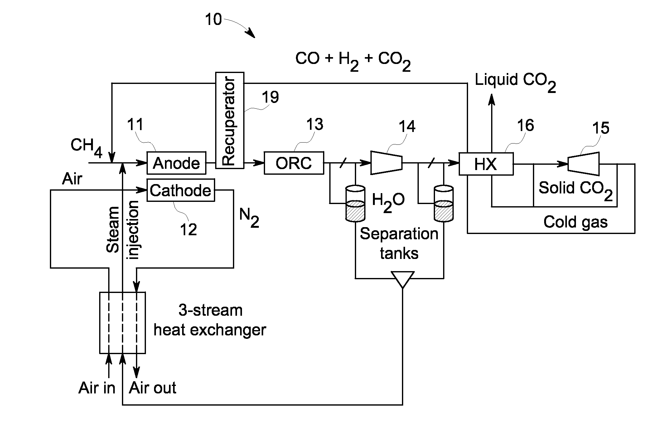
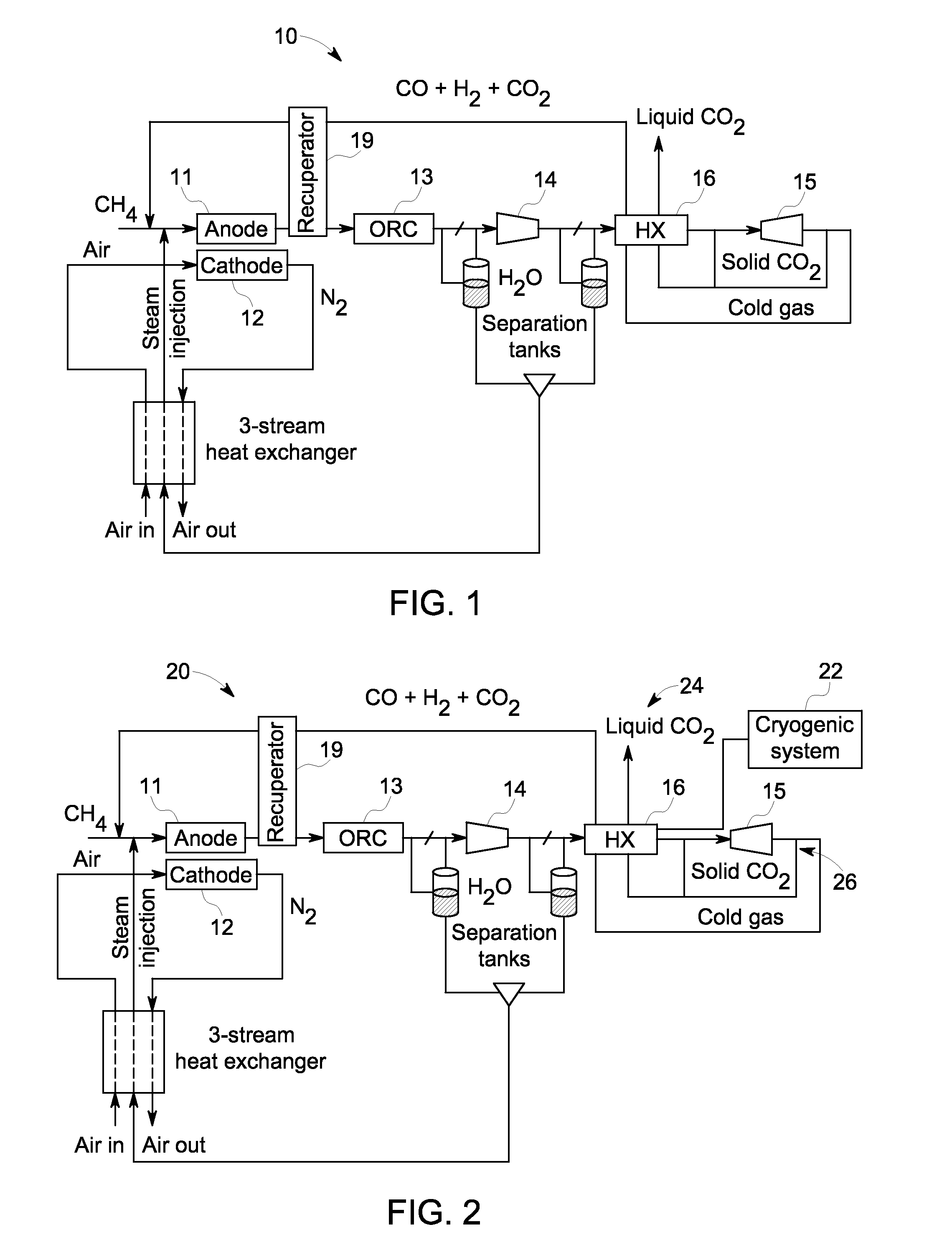
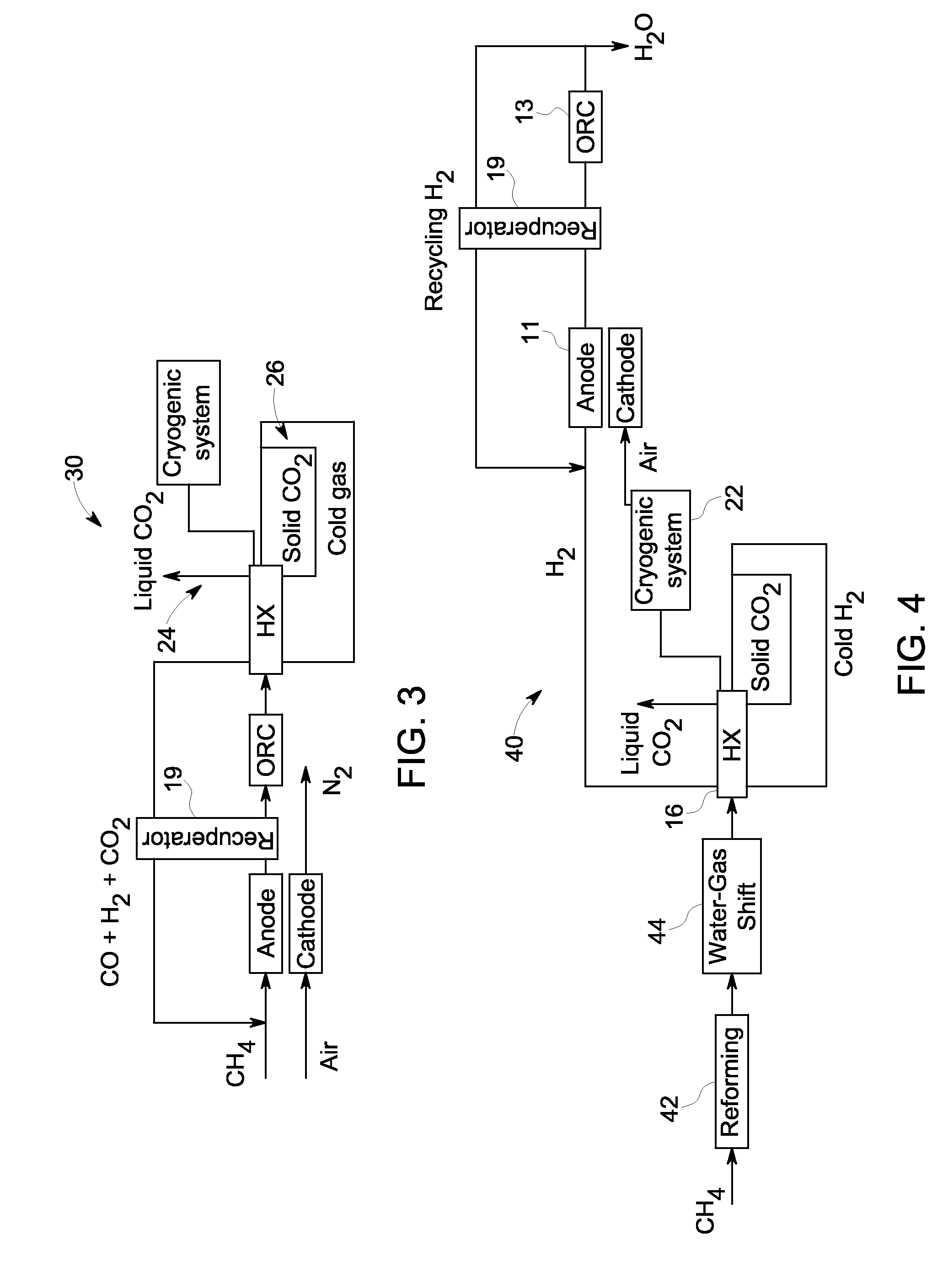
[0044]FIG. 1 is a simplified diagram illustrating a solid-oxide fuel cell (SOFC) recirculation complex 10 according to one embodiment. Recirculation complex 10 comprises an SOFC that includes an anode 11 and a cathode 12. Heat from the anode 11 exhaust drives a Rankine heat cycle referred to herein as Organic Rankine cycle (ORC) 13 to produce power. The ORC exhaust gas is applied to a compressor 14 that functions to compress the ORC exh...


PUM


Abstract

A system and method are provided for boosting overall performance of a fuel cell while simultaneously separating a nearly pure stream of CO2 for sequestration or for use in generating electrical power to further increase overall efficiency of the process. The system and method employ a heat exchanger system configured to generate a stream of fuel that is returned to the inlet of the fuel cell anode with a higher molar concentration of carbon monoxide (CO) and hydrogen (H2) fuel than was initially present in the fuel cell anode outlet.

Description

BACKGROUND[0001]This invention relates generally to solid-oxide fuel cells (SOFCs), and more particularly to systems and methods for boosting overall performance of a solid-oxide fuel cell (SOFC) while simultaneously separating a nearly pure stream of CO2 for sequestration or for use in generating electrical power to further increase overall efficiency of the process.[0002]Fuel cells are electrochemical energy conversion devices that have demonstrated a potential for relatively high efficiency and low pollution in power generation. A fuel cell generally provides a direct current (dc) which may be converted to alternating current (ac) via for example, an inverter. The dc or ac voltage can be used to power motors, lights, and any number of electrical devices and systems. Fuel cells may operate in stationary, semi-stationary, or portable applications. Certain fuel cells, such as solid oxide fuel cells (SOFCs), may operate in large-scale power systems that provide electricity to satisfy...

Claims


Application Information

Patent Timeline
IPC IPC(8): H01M8/06
CPCH01M8/04059H01M8/04097H01M8/04111Y02E60/525H01M2008/1293Y02E60/50H01M8/0668
Inventor LEHAR, MATTHEW ALEXANDERSHAPIRO, ANDREW PHILIPBIEDERMAN, BRUCE PHILIPLISSIANSKI, VITALI VICTORPETER, ANDREW MAXWELLALINGER, MATTHEW JOSEPHHUDY, LAURA MICHELESHISLER, ROGER ALLEN
Owner CUMMINS ENTERPRISE LLC
Learn More