Occlusion-crossing devices, imaging, and atherectomy devices

a technology of occlusion crossing and atherectomy, which is applied in the field of catheters, can solve the problems of sharp edges, rough edges, and other dissection, and achieve the effects of enhancing imaging, enhancing catheter flexibility, and facilitating construction

a technology of occlusion crossing and atherectomy, which is applied in the field of catheters, can solve the problems of sharp edges, rough edges, and other dissection, and achieve the effects of enhancing imaging, enhancing catheter flexibility, and facilitating construction

US20120253186A1Active Publication Date: 2012-10-04AVINGER

Image

  • Occlusion-crossing devices, imaging, and atherectomy devices
  • Occlusion-crossing devices, imaging, and atherectomy devices
  • Occlusion-crossing devices, imaging, and atherectomy devices

Examples


Embodiment Construction

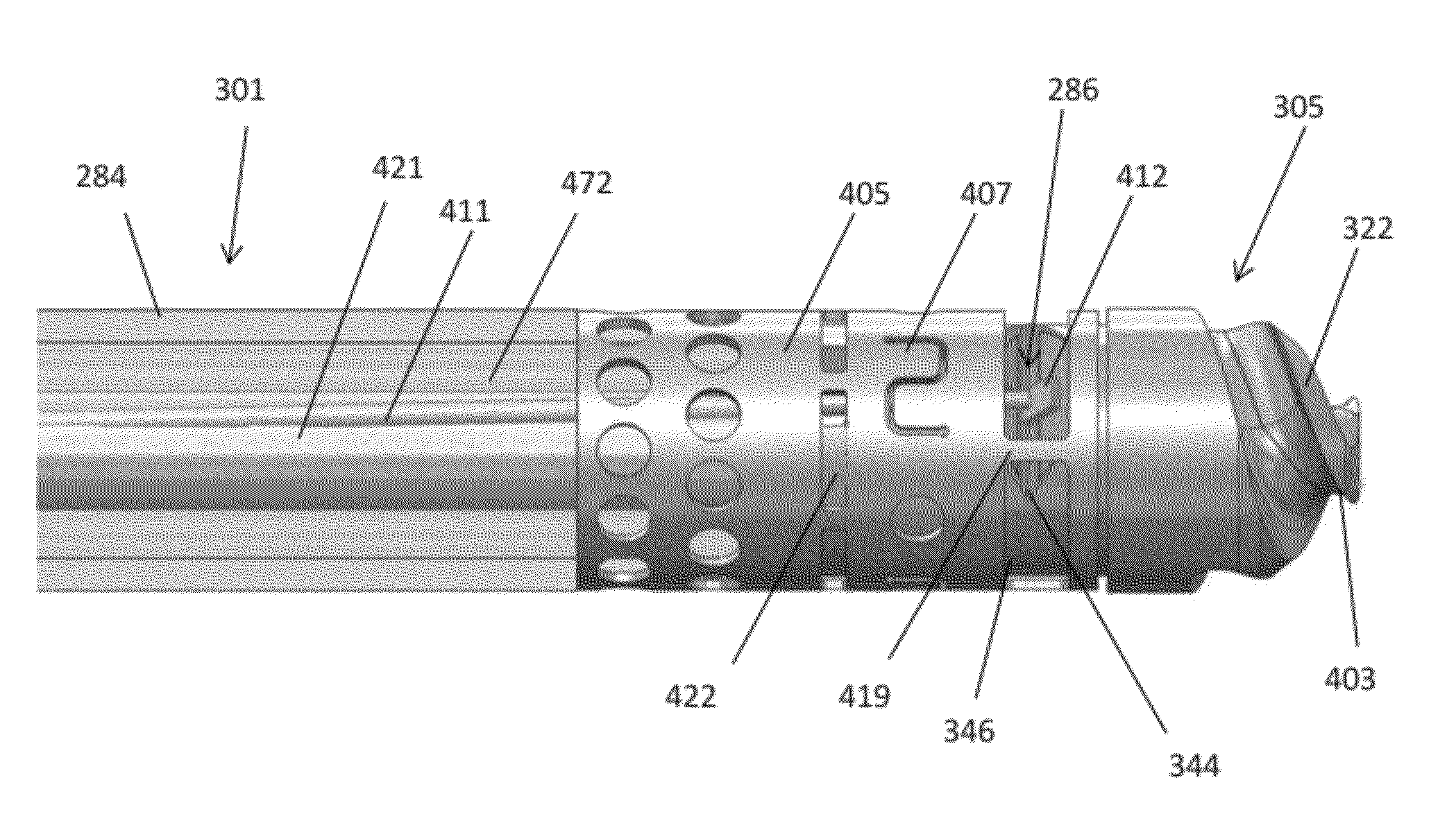
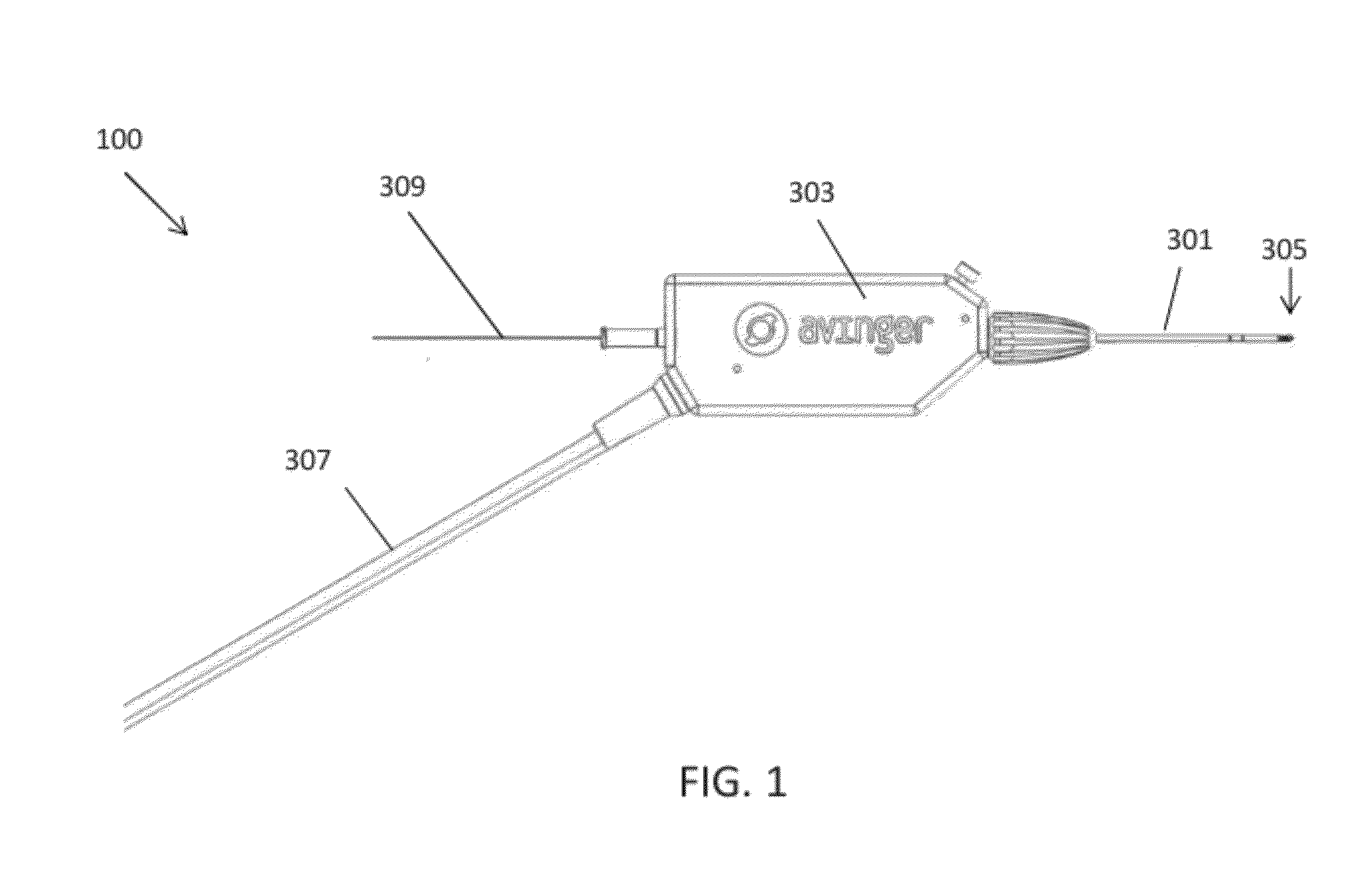
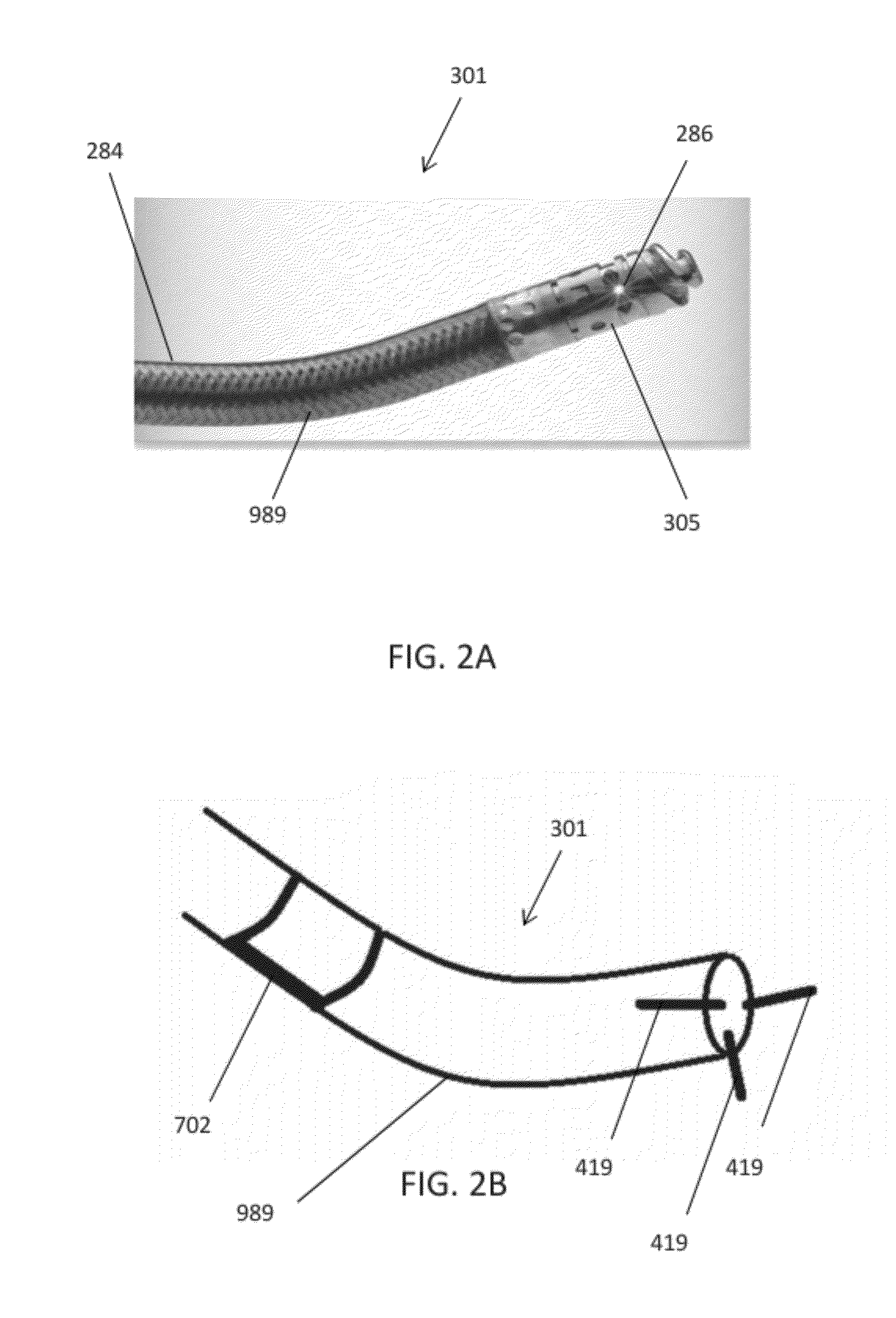
[0075]The catheters described herein typically include one or more imaging sensors at the distal end that may be rotated independently of the elongate body of a catheter. An imaging sensor may include an optical coherence tomography (OCT) sensor. The rotating distal end may also include one or more tissue cutting or dissecting surfaces that may aid the catheter in advancing within occluded regions of a vessel.

[0076]Examples of the types of catheters that are described herein in detail include: (1) guidewire support / placement catheters; (2) support / placement imaging catheters; (3) occlusion crossing catheters (4) occlusion crossing imaging catheters; (5) atherectomy catheters; and (6) atherectomy imaging catheters.

[0077]Two sections are included below. Part I describes catheters, including occlusion crossing catheters, that may be used as guidewire placement and support catheters. In particular, Part I describes catheters configured for imaging from the inside of a vessel, such as an...


PUM


Abstract

The present invention relates to: (1) guidewire support / placement catheters; (2) support / placement catheters with imaging; (3) atherectomy catheters, (4) atherectomy catheters with imaging, (5) occlusion crossing catheters, and (6) occlusion crossing catheters with imaging as well as methods for using them to treat disorders (and particularly peripheral artery disease) and systems including them.

Description

CROSS REFERENCE TO RELATED APPLICATIONS[0001]This application claims priority to U.S. Provisional Application No. 61 / 468,396, filed Mar. 28, 2011 and titled “OCCLUSION-COURSING DEVICES, IMAGING, AND ATHERECTOMY DEVICES”, which is herein incorporated by reference in its entirety.[0002]This patent application may be related to one or more of the following pending patent applications: U.S. patent application Ser. No. 12 / 689,748, filed Jan. 19, 2010 and titled “GUIDEWIRE SUPPORT CATHETER”, Publication No. US-2010-0274270-A1; U.S. patent application Ser. No. 12 / 108,433, filed Apr. 23, 2008 and titled “CATHETER SYSTEM AND METHOD FOR BORING THROUGH BLOCKED VASCULAR PASSAGES”, now U.S. Pat. No. 8,062,316; U.S. patent application Ser. No. 12 / 272,697, filed Nov. 17, 2008 and titled “DUAL-TIP CATHETER SYSTEM FOR BORING THROUGH BLOCKED VASCULAR PASSAGES”, Publication No. US-2010-0125253-A1, now abandoned; U.S. patent application Ser. No. 12 / 829,277, filed Jul. 1, 2010 and titled “ATHERECTOMY CA...

Claims


Application Information

Patent Timeline
04 Oct 2012
Publication
US20120253186A1
IPC
A61B6/00; A61B17/22
CPC
A61B8/0841; A61B19/5225; A61B2017/00778; A61B5/0035; A61B2019/5466; A61B6/485; A61B5/0062; A61B2017/00057
Inventors
SIMPSON, JOHN B.; PATEL, HIMANSHU N.