
Organic light emitting diode display and manufacturing method thereof

Active Publication Date: 2012-10-11
SAMSUNG DISPLAY CO LTD
View PDF2 Cites 9 Cited by
  • Summary
  • Abstract
  • Description
  • Claims
  • Application Information

AI Technical Summary

Benefits of technology

[0009]Aspects of embodiments of the present invention relate to an organic light emitting diode (OLED) display that can be manufactured through a simple process while reducing cost, and a manufacturing method thereof.
[0024]According to yet another exemplary embodiment of the present invention, a manufacturing method of an organic light emitting diode (OLED) display is provided. The method includes: forming an organic emission layer and a thin film encapsulation layer that covers the organic emission layer and contains a di-functional ultraviolet (UV) oligomer and a hexa-functional UV oligomer on a substrate including a pixel area and a peripheral area; adhering a laminating film comprising one or more adhesive layers and an upper protective layer covering an upper adhesive layer from among the adhesive layers on the thin film encapsulation layer; radiating ultraviolet (UV) light on the laminating film and the thin film encapsulation layer that corresponds to the peripheral area of the substrate to decrease adhesion between the thin film encapsulation layer and the organic emission layer corresponding to the peripheral area of the substrate; and peeling the laminating film and the thin film encapsulation layer corresponding to the peripheral area of the substrate from the organic emission layer to maintain the laminating film and the thin film encapsulation layer corresponding to the pixel area of the substrate.
[0030]According to exemplary embodiments of the present invention as discussed above, a pattern change of the laminating film due to a model change of the OLED display can be easily performed through such a laminating film patterning process. Further, since no additional cutting device or press device is required, the process time can be shortened and the process cost can be reduced.

Problems solved by technology

However, the photolithography process may cause damage to the OLED display under the laminating film.
This can lead to increased process time and cost.
Further, when using such laminating film pattering processes, a pattern change due to a model change of the OLED display cannot be easily performed.

Method used


Image

  • Organic light emitting diode display and manufacturing method thereof
  • Organic light emitting diode display and manufacturing method thereof
  • Organic light emitting diode display and manufacturing method thereof

Examples


Embodiment Construction

[0039]The present invention will be described more fully hereinafter with reference to the accompanying drawings, in which exemplary embodiments of the invention are shown. As those skilled in the art would realize, the described embodiments may be modified in various different ways, all without departing from the spirit or scope of the present invention.

[0040]In the description, some of the parts that are not relevant are omitted, and like reference numerals designate like elements throughout the specification. In addition, the size and thickness of each component shown in the drawings are for ease of understanding and description, but the present invention is not limited thereto.

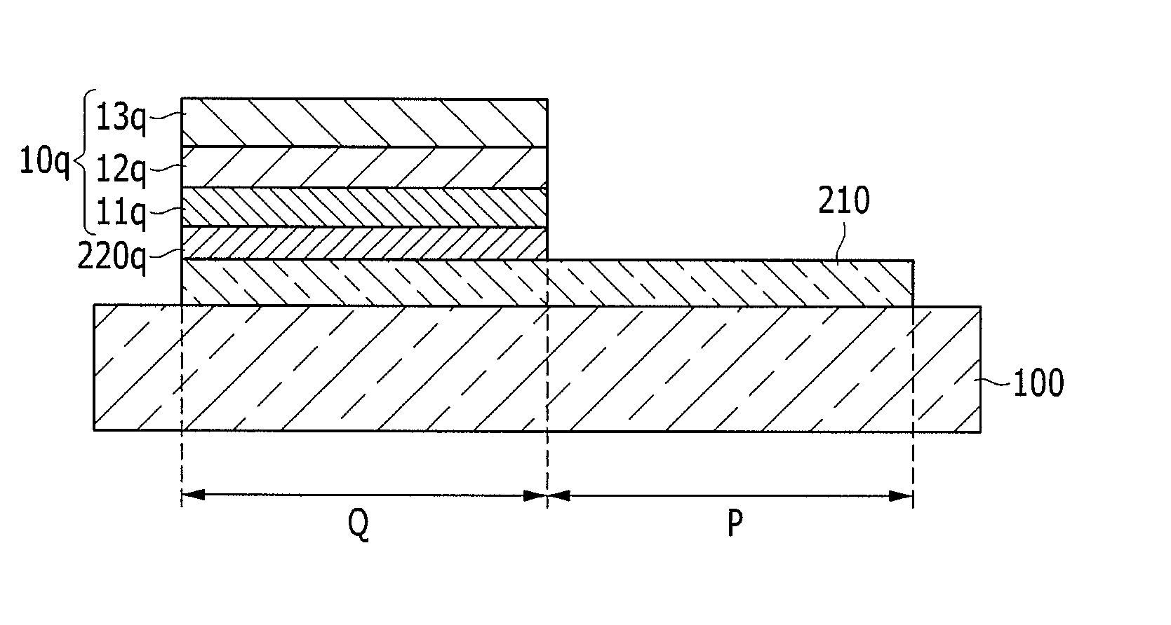
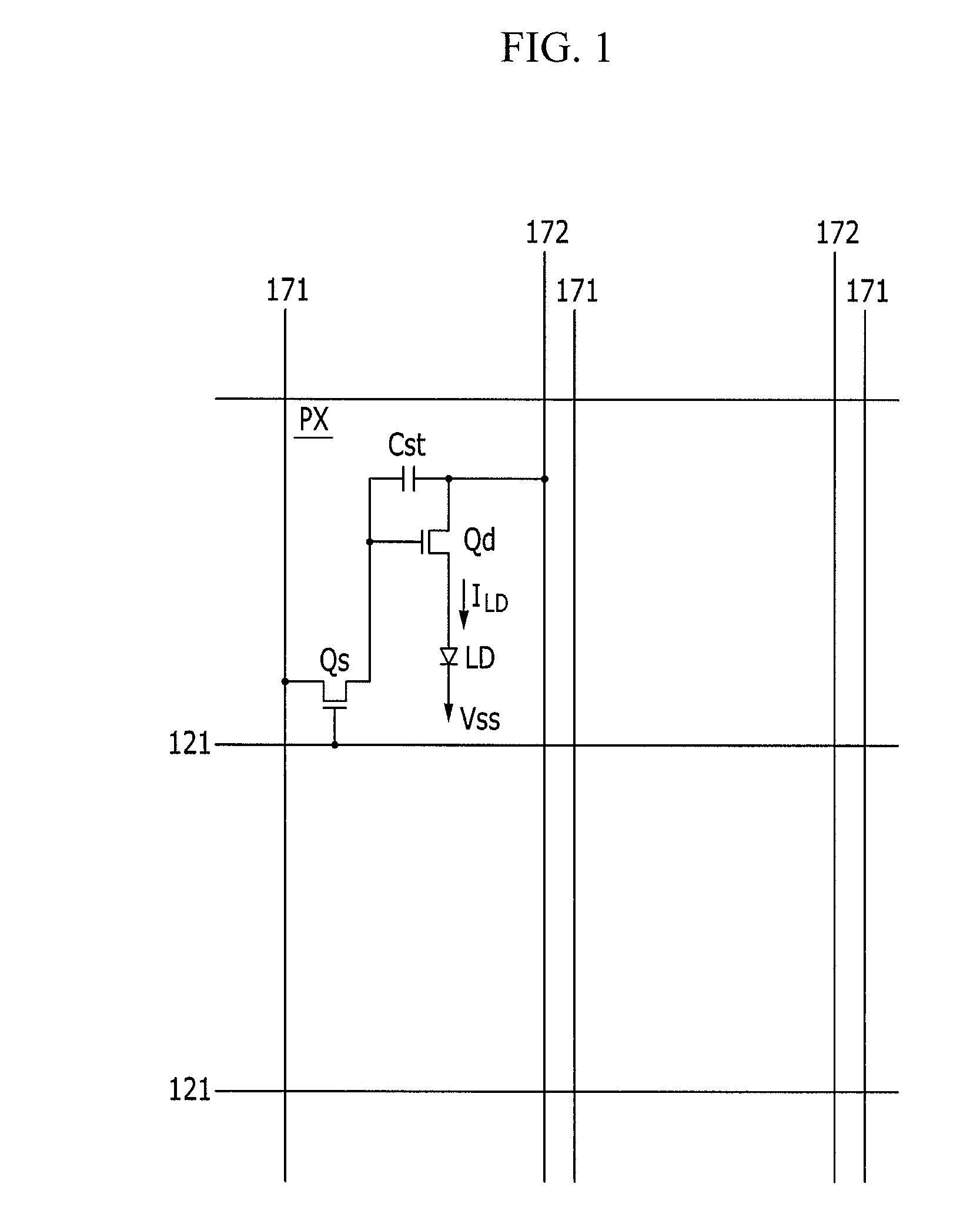
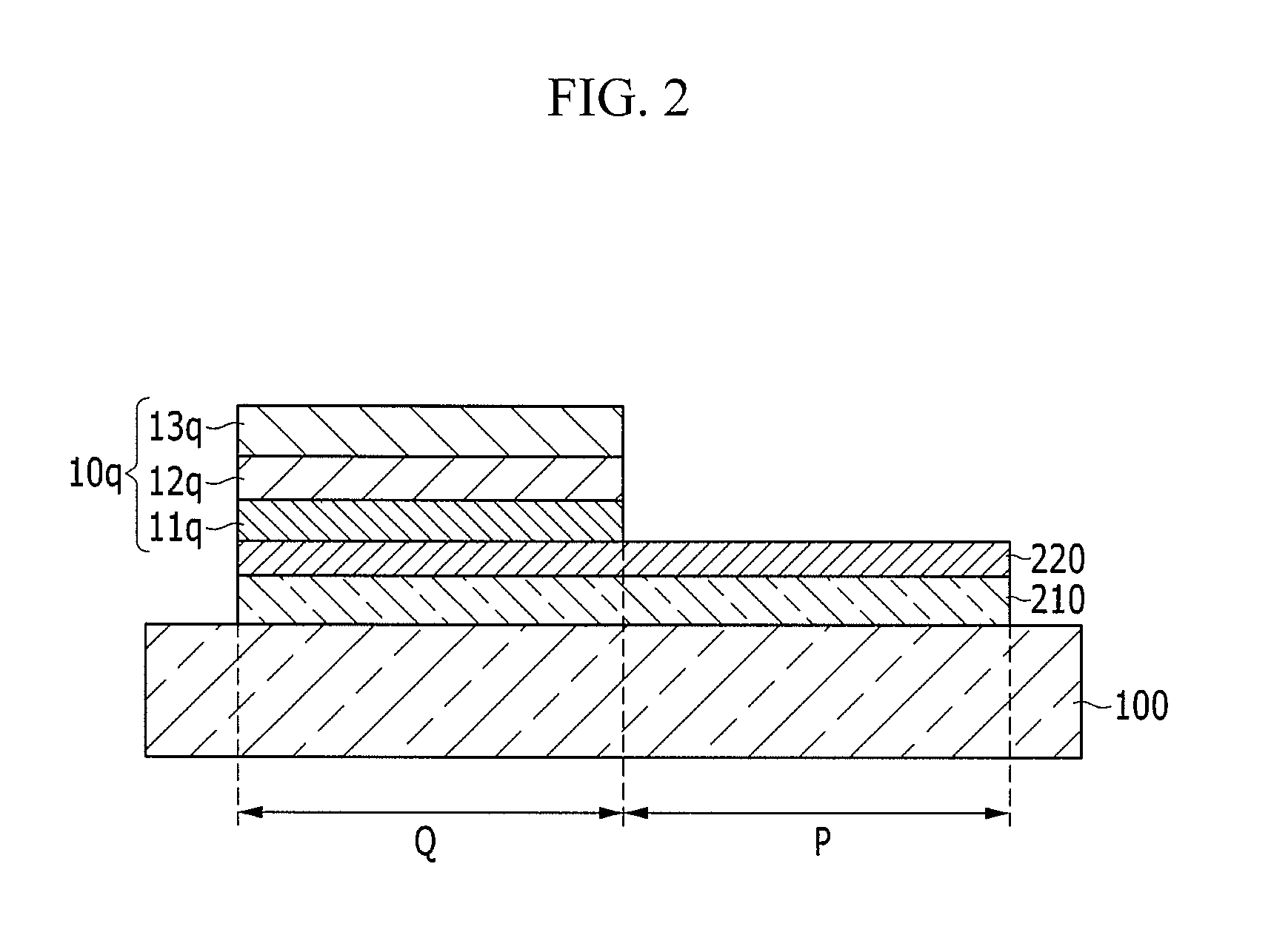
[0041]Referring to FIGS. 1-2, an organic light emitting diode (OLED) display according to a first exemplary embodiment will be described in detail. FIG. 1 is an equivalent circuit diagram of the OLED display, and FIG. 2 is a cross-sectional view of the OLED display.

[0042]As shown in FIG. 1, the OLED displa...


PUM

PropertyMeasurementUnit
Concentrationaaaaaaaaaa
Adhesion strengthaaaaaaaaaa
Areaaaaaaaaaaa

Abstract

A manufacturing method of an OLED display is provided. The method includes: forming an organic emission layer and a thin film encapsulation layer covering the organic emission layer on a substrate including a pixel area and a peripheral area; adhering a laminating film including a plurality of adhesive layers and an upper protective layer that covers an upper adhesive layer from among the adhesive layers on the thin film encapsulation layer, a lower adhesive layer from among the adhesive layers contacting the thin film encapsulation layer; radiating UV light on the laminating film that corresponds to the peripheral area of the substrate to decrease adhesion between the lower adhesive layer and the thin film encapsulation layer corresponding to the peripheral area; and peeling the laminating film corresponding to the peripheral area from the thin film encapsulation layer to maintain the laminating film that corresponds to the pixel area.

Description

CROSS-REFERENCE TO RELATED APPLICATIONS[0001]This application claims priority to and the benefit of Korean Patent Application No. 10-2011-0033397, filed in the Korean Intellectual Property Office on Apr. 11, 2011, the entire content of which is incorporated herein by reference.BACKGROUND[0002]1. Field[0003]Aspects of embodiments of the present invention relate generally to an organic light emitting diode (OLED) display and a manufacturing method thereof.[0004]2. Description of the Related Art[0005]An organic light emitting diode (OLED) display includes two electrodes and an organic emission layer disposed between the two electrodes. Electrons injected from one electrode and holes injected from the other electrode are coupled with each other in the organic emission layer to form excitons. The excitons emit light while passing from an excited state to a ground state.[0006]In order to protect such an OLED display, a laminating film may be formed on a surface of the OLED display. The la...

Claims


Application Information

Patent Timeline
IPC IPC(8): H01L51/50B32B37/14B32B38/08B32B38/10
CPCH01L51/5253H01L2227/323B32B37/1207B32B2457/206B32B38/10B32B2037/1253B32B2310/0831B32B38/06H10K59/1201H10K59/873B32B37/0007H10K50/844
Inventor LEE, SO-YOUNGCHO, YOON-HYEUNGOH, MIN-HOLEE, BYOUNG-DUKKIM, YONG-TAKCHO, SANG-HWANCHUNG, YUN-AHSONG, SEUNG-YONGLEE, JONG-HYUK
Owner SAMSUNG DISPLAY CO LTD
Learn More