
Switch level circuit with dead time self-adapting control

a dead time control and switch level technology, applied in pulse generators, pulse manipulation, pulse techniques, etc., can solve problems such as power loss, inappropriate dead time, and extremely long or short dead tim

Inactive Publication Date: 2012-10-11
SOUTHEAST UNIV
View PDF3 Cites 16 Cited by
  • Summary
  • Abstract
  • Description
  • Claims
  • Application Information

AI Technical Summary

Benefits of technology

[0012]The present invention can regulate the dead time dynamically, reduce or eliminate any feed-through loss in high-side transistor and low-side transistor of rectifier and power devices and gate-on loss in body diode, and implements an optimal dead time, so as to reduce power loss. The self-adapting dead time control circuit has advantages over existing ordinary dead time control circuits in many aspects:
[0013]1. Fast speed of self-adaption:, the dead time can be regulated in the second operating cycle after a bad dead time is detected and can be adjusted to an optimal value after 3-4 cycles.
[0014]2. High self-adapting control accuracy: since the dead time is regulated by directly detecting the gate-on time of body diode instead of indirectly detecting the factors that have influence on optimal dead time, the circuit can operate at high accuracy in various working environments, regardless of the manufacturing technology.
[0015]3. The circuit has simple structure, very low power consumption, very small layout area, and very low control complexity, etc., and can achieve self-adapting dead time control at a low cost.
[0016]4. Wide applicability: the present invention detects the gate-on time of body diode of a synchronous rectifying transistor, and doesn't require any design adjust to the switching power supply converter with specific control mode; therefore, it is applicable to any switching converter with a synchronous rectifying transistor.

Problems solved by technology

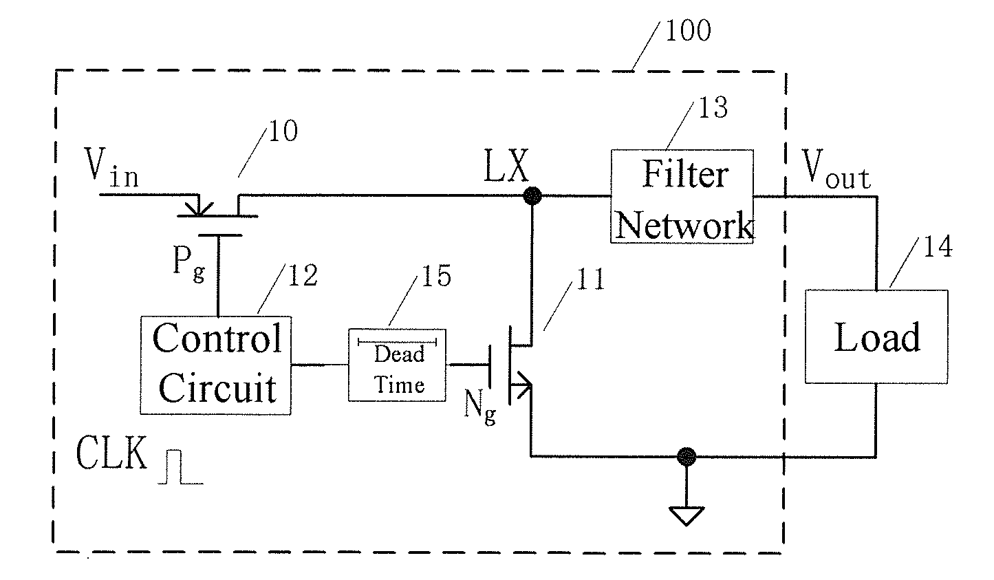
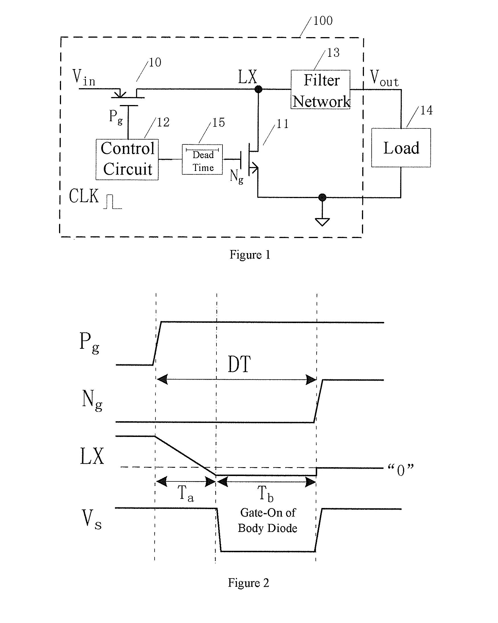
In switching power supply conversion circuits with a synchronous rectifier, one of the major factors that result in power loss is inappropriate dead time in the high-side control transistor and the low-side synchronous rectifying transistor.
A fixed dead time control method will cause extremely long or short dead time and therefore result in gate-on of the body diode of rectifying transistor 11 or gate-on of the low-side synchronous rectifying transistor in positive direction.

Method used


Image

  • Switch level circuit with dead time self-adapting control
  • Switch level circuit with dead time self-adapting control
  • Switch level circuit with dead time self-adapting control

Examples


embodiments

[0045]FIG. 9 shows one embodiment of self-adapting dead time control, and the sampling circuit employs the structure shown in the box 16 enclosed by dotted lines. Wherein, an NMOS transistor 161, with the gate electrode grounded and the source electrode connected to the node LX, is used as a sampling transistor; a PMOS transistor 165, with the drain end connected to the diode, is used as the load for the sampling transistor; the gate electrodes of PMOS transistors 166 and 167 are connected to a bias voltage Vbias at a fixed potential, the drain current of the PMOS transistor 167 is used as a charging current source for sampling, and after the drain current of the PMOS transistor 166 passes through NMOS current mirror then provides a discharging current source for sampling; a switching transistor 162 is used as a charging switch, when the sampling transistor 161 gates-on as a result of a negative voltage occurs at the switching node LX, the enabling signal Kch of the sampling chargin...


PUM


Abstract

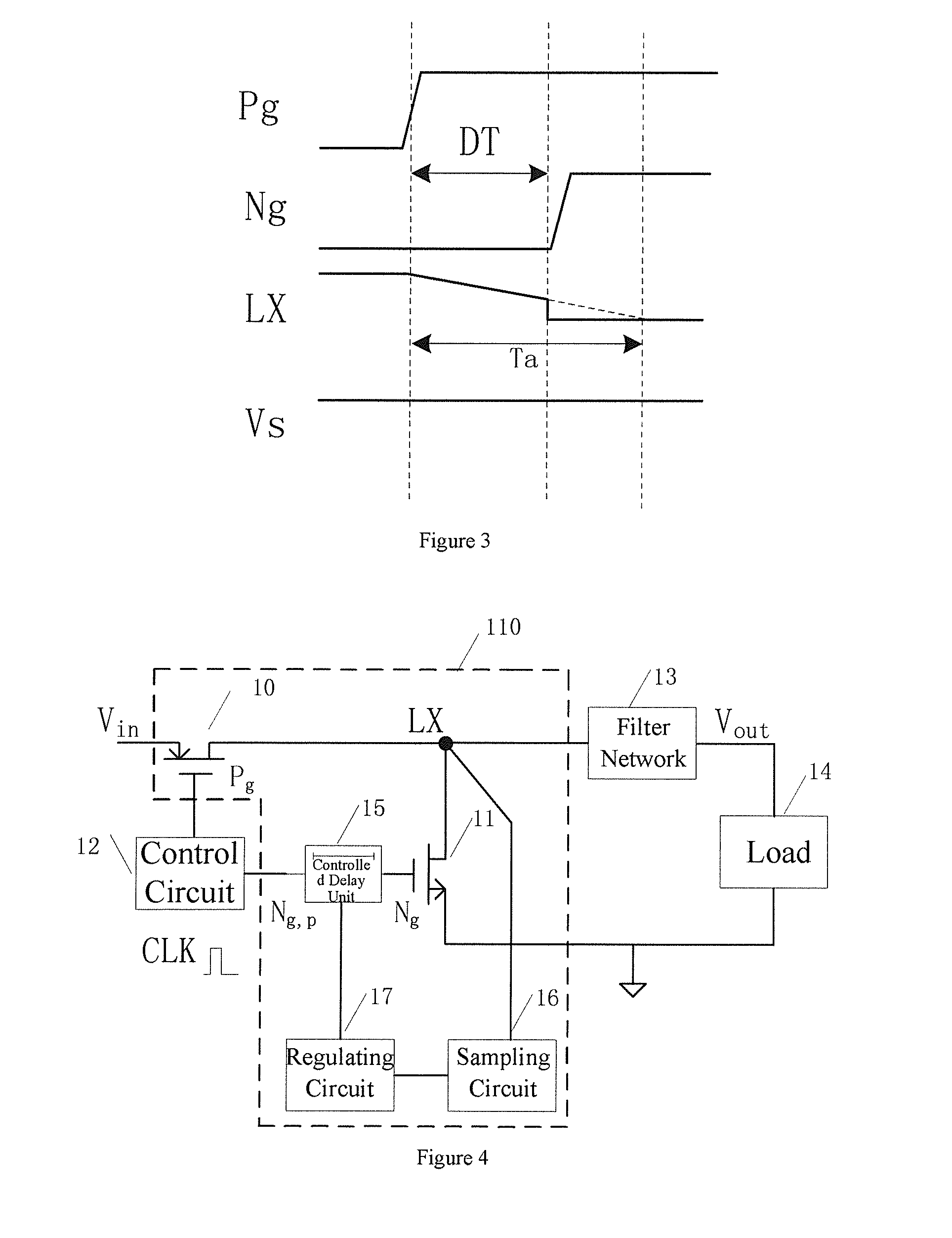
A switch level circuit (110) with dead time self-adapting control, which minimizes the switching loss in a switching power supply converter with synchronous rectification by changing a dead time between a high-side control transistor (10) and a low-side synchronous rectifying transistor (11). The switch level circuit (110) includes the high-side control transistor (10) and the low-side synchronous rectifying transistor (11) which are controlled to be on and off by external control signals, and a waveform with a given duty cycle is outputted at a node (LX) between the two transistors. The switch level circuit (110) also includes a control module for adjusting the dead time. The control module comprises a sampling circuit (16) for detecting the current dead time at the node (LX), an adjusting circuit (17) for buffering and converting the sampling voltage sampled by the sampling circuit (16), and a controlled delay unit (15) equipped with an external control input terminal, wherein the controlled delay unit (15) delays an external control signal and outputs the delayed signal to a controlled terminal of the low-side synchronous rectifying transistor (11) as a control signal. The switch level circuit (110) has simple structure, better performance and wide application range.

Description

CROSS-REFERENCE TO RELATED APPLICATION(S)[0001]This application is a National Phase Patent Application of International Patent Application Number PCT / CN2010 / 078103, filed on Oct. 26, 2010, which claims priority to and the benefit of Chinese Patent Application Number 201010248404.4, filed on Aug. 6, 2010.FIELD OF THE INVENTION[0002]The present invention relates to a switch level circuit with self-adapting dead time control capability, in particular to a switch level circuit with self-adapting dead time control capability, which can reduce the switching loss in switching power supply converters with a synchronous rectifier, and improve the power supply conversion efficiency.BACKGROUND OF THE INVENTION[0003]In switching power supply converters, though a synchronous rectifier involves complex control, it can reduce switching loss. In switching power supply conversion circuits with a synchronous rectifier, one of the major factors that result in power loss is inappropriate dead time in t...

Claims


Application Information

Patent Timeline
IPC IPC(8): H03K3/017
CPCH02M3/1588H02M2001/0048Y02B70/1491Y02B70/1466H02M2001/385Y02B70/10H02M1/0048H02M1/385
Inventor XU, SHENSUN, WEIFENGYANG, MIAOLIU, SICHAOJIN, YOUSHANLU, SHENGLISHI, LONGXING
Owner SOUTHEAST UNIV
Learn More