Eureka AIR delivers breakthrough ideas for toughest innovation challenges, trusted by R&D personnel around the world.

Multi-Anode Solid Electrolytic Capacitor Assembly

a solid electrolytic capacitor and multi-anode technology, applied in the direction of electrolytic capacitors, fixed capacitor details, fixed capacitors, etc., can solve the problems of poor stability of such solid electrolytes at high temperatures, poor electrical performance, and problems that remain

Active Publication Date: 2012-10-11
KYOCERA AVX COMPONENTS CORP
View PDF7 Cites 17 Cited by
  • Summary
  • Abstract
  • Description
  • Claims
  • Application Information

AI Technical Summary

Problems solved by technology

Unfortunately, however, the stability of such solid electrolytes is poor at high temperatures due to the tendency to transform from a doped to an un-doped state, or vice versa.
Despite the benefits achieved, however, problems nevertheless remain.
Due to its large size, however, the capacitor element is mechanically instable, particularly under extreme conditions (e.g., high temperature of above about 175° C. and / or high voltage of above about 35 volts), which leads to leading to delamination and poor electrical performance.

Method used


Image

  • Multi-Anode Solid Electrolytic Capacitor Assembly
  • Multi-Anode Solid Electrolytic Capacitor Assembly
  • Multi-Anode Solid Electrolytic Capacitor Assembly

Examples


example 1

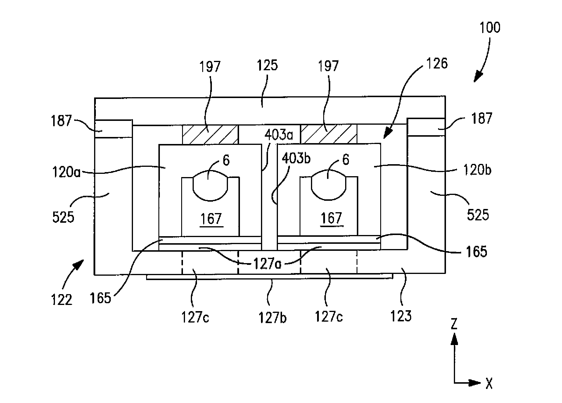
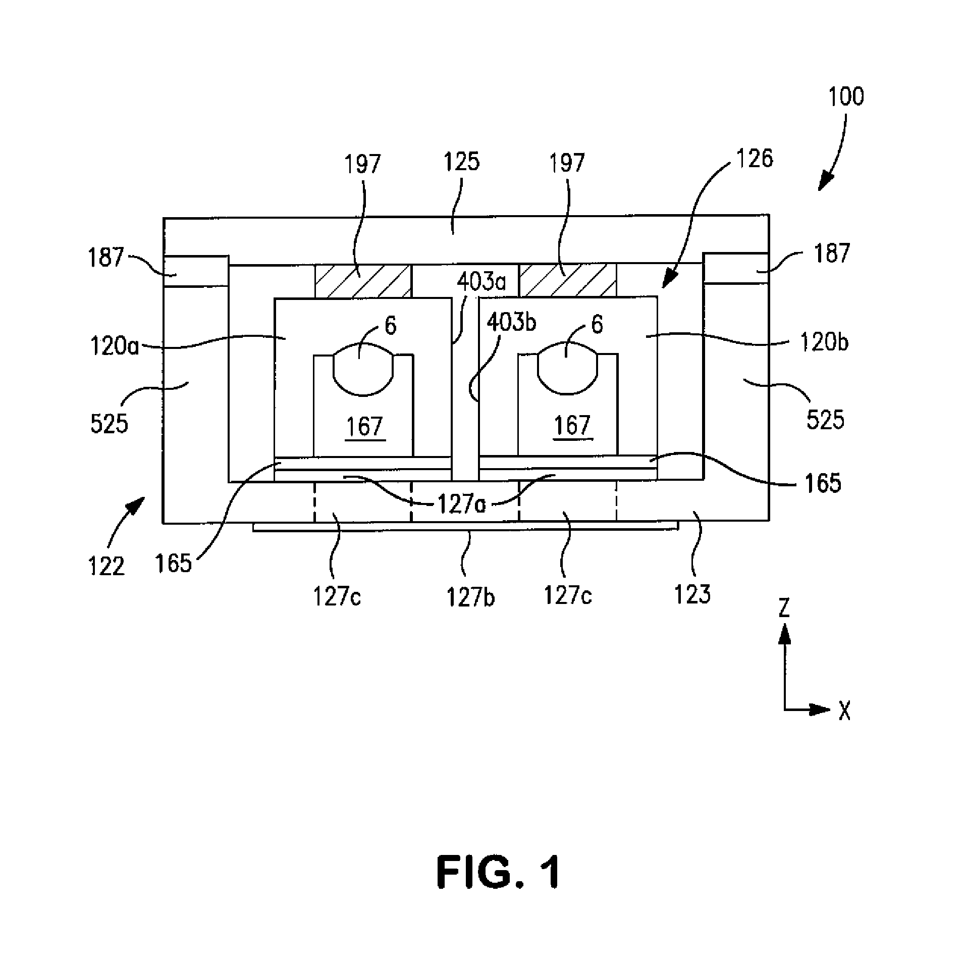
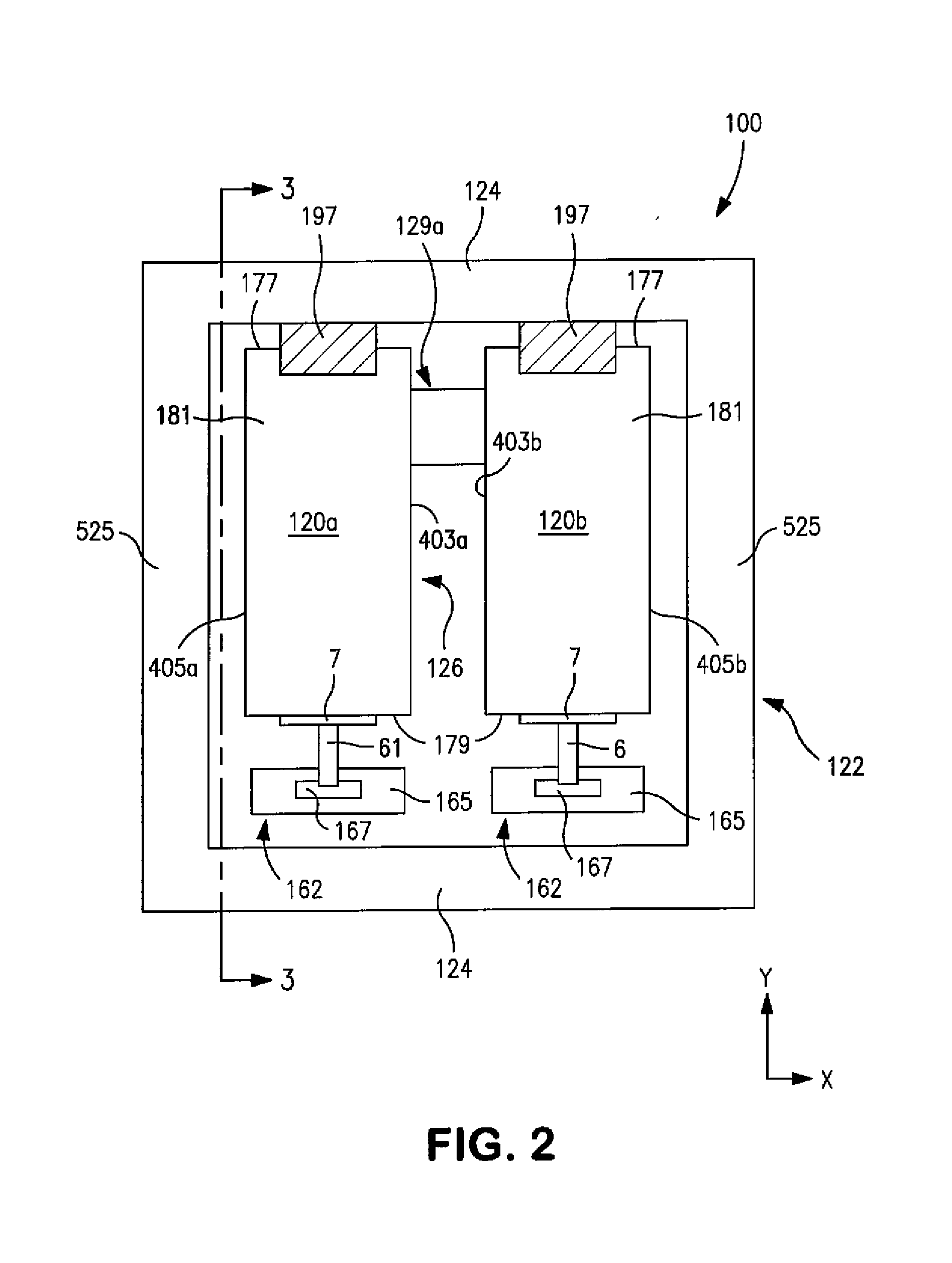
[0080]A tantalum anode (4.80 mm×5.25 mm×2.60 mm) was anodized at 30V in a liquid electrolyte to 150 μF. A conductive polymer coating was then formed by dipping the entire anode into a poly(3,4-ethylenedioxythiophene) (“PEDT”) dispersion (Clevios™ K, solids content of 1.1%). The part was then dried at 125° C. for 20 minutes. This process was repeated 10 times. Thereafter, the part was dipped at a speed of 0.1 mm / s into a PEDT dispersion (solids content of 2.8%) so that the dispersion reached the shoulder of the part as shown in FIG. 3. The part was left in the dispersion for 10 seconds, dried at 125° C. for 30 minutes, and then cooled down to room temperature. This process was repeated 5 times. The part was then coated with graphite and silver. A copper-based leadframe material was used to finish the assembly process. A single cathode connective member was attached to the lower surface of the capacitor element using a silver adhesive. The tantalum wire of the capacitor element was th...

example 2

[0082]A tantalum anode (4.80 mm×10.50 mm×2.60 mm) was anodized at 30V in a liquid electrolyte to 150 μF. A conductive polymer coating was then formed by dipping the entire anode into a poly(3,4-ethylenedioxythiophene) (“PEDT”) dispersion (Clevios™ K, solids content of 1.1%). The part was then dried at 125° C. for 20 minutes. This process was repeated 10 times. Thereafter, the part was dipped at a speed of 0.1 mm / s into a PEDT dispersion (solids content of 2.8%) so that the dispersion reached the shoulder. The part was left in the dispersion for 10 seconds, dried at 125° C. for 30 minutes, and then cooled down to room temperature. This process was repeated 5 times. The part was then coated with graphite and silver. Multiple parts (50) were then formed from the capacitor elements in the same manner described above.

[0083]The parts of Examples 1 and 2 were then tested for electrical performance (i.e., capacitance (“CAP”) and equivalent series resistance (“ESR”)), before and after “vibra...


PUM


Abstract

A capacitor assembly that is stable under extreme conditions is provided. A capacitor assembly that is capable of achieving a high capacitance and yet remain thermally and mechanically stable under extreme conditions. Even at high capacitance values, good mechanical stability can be achieved by connecting multiple individual capacitor elements to the housing of the assembly. Without intending to be limited by theory, it is believed that the use of multiple elements increases the surface area over which the elements are connected to the housing. Among other things, this allows the elements to dissipate vibrational forces incurred during use over a larger area, which reduces the likelihood of delamination. The capacitor elements are also enclosed and hermetically sealed within a single housing in the presence of a gaseous atmosphere that contains an inert gas, thereby limiting the amount of oxygen and moisture supplied to the solid electrolyte of the capacitor elements. Through the combination of the features noted above, the capacitor assembly is able to better function under extreme conditions.

Description

BACKGROUND OF THE INVENTION[0001]Electrolytic capacitors (e.g., tantalum capacitors) are increasingly being used in the design of circuits due to their volumetric efficiency, reliability, and process compatibility. For example, one type of capacitor that has been developed is a solid electrolytic capacitor that includes an anode (e.g., tantalum), a dielectric oxide film (e.g., tantalum pentoxide, Ta2O5) formed on the anode, a solid electrolyte layer, and a cathode. The solid electrolyte layer may be formed from a conductive polymer, such as described in U.S. Pat. Nos. 5,457,862 to Sakata, et al., 5,473,503 to Sakata, et al., 5,729,428 to Sakata, et al., and 5,812,367 to Kudoh, et al. Unfortunately, however, the stability of such solid electrolytes is poor at high temperatures due to the tendency to transform from a doped to an un-doped state, or vice versa. In response to these and other problems, capacitors have been developed that are hermetically sealed to limit the contact of ox...

Claims


Application Information

Patent Timeline
Patent Type & Authority Applications(United States)
IPC IPC(8): H01G4/224
CPCH01G9/012H01G9/06H01G9/08H01G9/15Y02E60/13H01G11/48H01G2/065H01G4/228H01G9/26H01G2/103H01G9/025H01G9/04
Inventor ZEDNICKOVA, IVANA
Owner KYOCERA AVX COMPONENTS CORP
Why Eureka
Eureka Blog
Learn More