Method for calculating local specific energy absorption rate (SAR) in nuclear magnetic resonance

a technology of local specific energy absorption and nuclear magnetic resonance, which is applied in the direction of reradiation, measurement using nmr, instruments, etc., can solve the problems of body tissue heating and other adverse effects, alterations in visual, auditory and neural functions, and no reliable method has been found to determine in vivo. , to achieve the effect of short period of tim

Active Publication Date: 2012-10-18
KONINKLIJKE PHILIPS ELECTRONICS NV
View PDF3 Cites 10 Cited by
  • Summary
  • Abstract
  • Description
  • Claims
  • Application Information

AI Technical Summary

Benefits of technology

[0008]It is an object of the present invention to provide a method which is suitable for application into a clinical setting. Particularly, it is the object of the present invention to provide a method by means of which SAR calculation is done in a relatively short period of time.

Problems solved by technology

During a MRI procedure, the patient absorbs a portion of a transmitted RF energy, which can result in body tissue heating and other adverse effects, such as alterations in visual, auditory and neural functions.
No reliable method has been found to determine in vivo the electric field and electric conductivity, and thus, the local SAR.
Patient specific models within this framework are not practicable due to the simulation times of several hours.
The uncertainties of such models require large safety margins, frequently leading to a potentially unnecessary increase of the repetition time, and thus, the total acquisition time.
A drawback of the known system is that the full simulation of coil and patient is very time consuming, in particular at least several hours, and thus not practicable in a clinical setting.

Method used


Image

  • Method for calculating local specific energy absorption rate (SAR) in nuclear magnetic resonance
  • Method for calculating local specific energy absorption rate (SAR) in nuclear magnetic resonance
  • Method for calculating local specific energy absorption rate (SAR) in nuclear magnetic resonance

Examples


Embodiment Construction

[0031]In the following description of the preferred embodiments, reference is made to the accompanying drawings which form a part thereof. Specific embodiments, in which the invention may be practiced, are shown in the following description by a way of illustration. It is also understood that other embodiments may be utilized and structural changes may be made without departing from the scope of the present invention. It is noted that the same reference signs will be used for indicating the same or similar parts in the several embodiments.

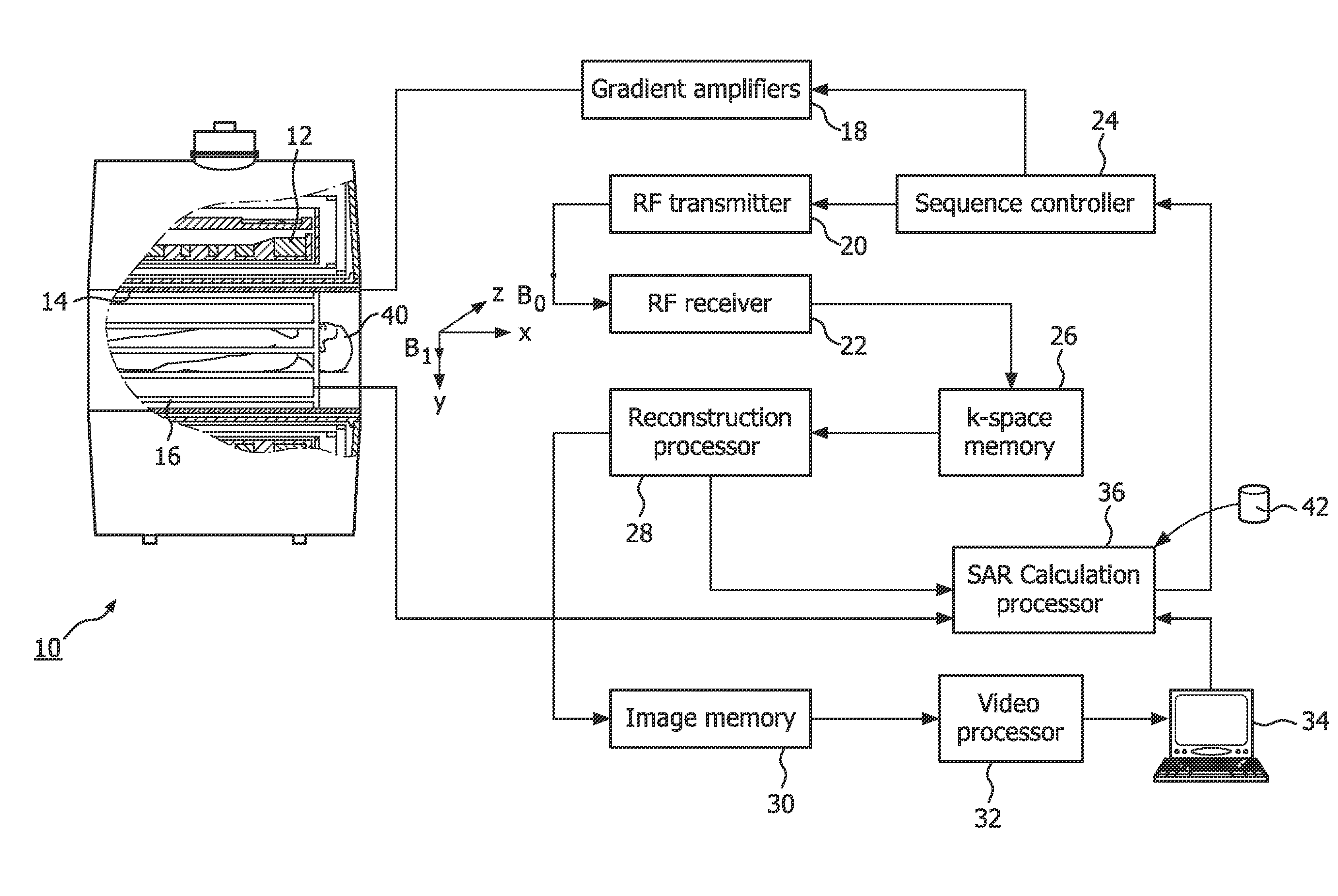
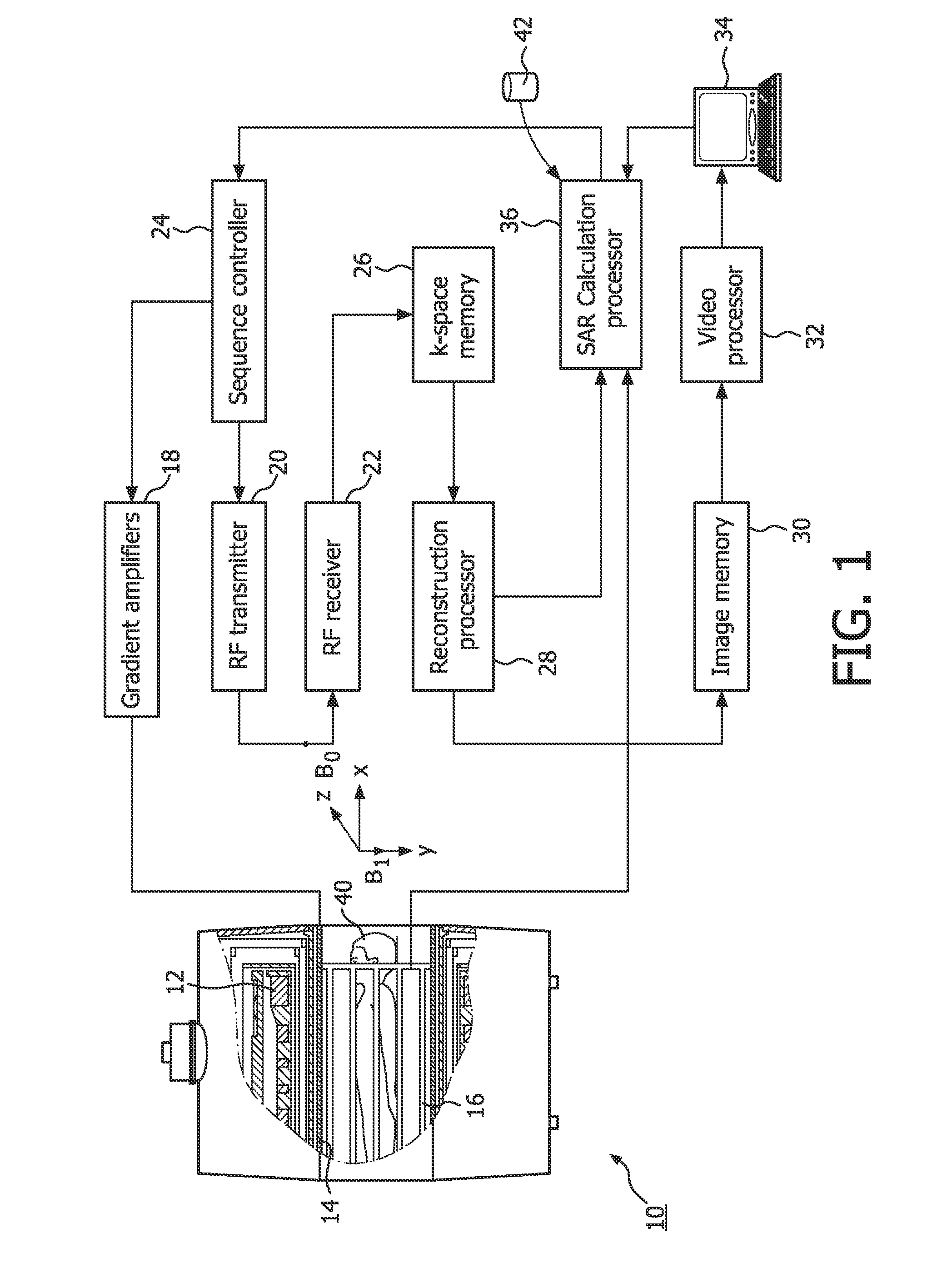
[0032]FIG. 1 schematically shows an exemplary embodiment of the magnetic resonance system according to the invention. A magnetic resonance scanner 10 is illustrated as a system that includes a solenoidal main magnet assembly 12. In this embodiment the system is a closed bore system. Other magnetic configurations, such as open configurations, of the magnetic resonance scanner are also possible. The main magnet assembly 12 produces a substantially co...


PUM


Abstract

A method for calculating a local specific energy absorption rate (SAR) on basis of an electric parameter and the mass density of a segmented geometry of an object and a magnetic field vector distribution of a radio frequency (RF) antenna. The values of the electric parameter and the mass density are pre-determined values, while the magnetic field vector distribution is estimated by a magnetic field mapping method based on a magnetic resonance (MR) scan. The magnetic field mapping method based on a magnetic resonance scan can be a Bi mapping method. The invention also relates to a magnetic resonance system by means of which SAR calculation can be done in a relatively short period of time. The invention also relates to a computer program comprising instructions for calculating a local specific energy absorption rate (SAR) according to the above mentioned method. The SAR calculation used in the above mentioned method, system and program is done in the relatively short period of time and as such is practicable in a clinical setting.

Description

FIELD OF THE INVENTION[0001]The invention relates to a method for calculating local specific energy absorption rate (SAR). The invention also relates to a magnetic resonance system and to a computer program comprising instructions for calculating a local specific energy absorption rate (SAR).BACKGROUND OF THE INVENTION[0002]Magnetic Resonance Imaging (MRI) is a medical imaging technique most commonly used in radiology to visualize detailed an internal structure and a function of a body of a human being. MRI uses a powerful magnetic field to align nuclear magnetization of usually hydrogen atoms in water in the body. Radio frequency (RF) fields are used to systematically alter the alignment of this magnetization, causing hydrogen nuclei to produce a rotating magnetic field detectable by a scanner. This detected signal can be manipulated by additional magnetic fields to build up enough information to construct an image of the body.[0003]During a MRI procedure, the patient absorbs a por...

Claims


Application Information

Patent Timeline
Patent Type & Authority Applications(United States)
IPC IPC(8): G01R33/483G01R33/34
CPCG01R33/246G01R33/288G01R33/5608G01R33/543G01R33/546G01R33/443
Inventor VOIGT, TOBIAS RATKOKATSCHER, ULRICHHOMANN, HANNO HEYKE
Owner KONINKLIJKE PHILIPS ELECTRONICS NV
Why Eureka
Try Eureka