Use of ventilation air methane exhausted during mining of non-combustible ore in a surface appliance

a technology of non-combustible ore and ventilation air, which is applied in the direction of gas removal, combustion types, lighting and heating apparatuses, etc., can solve the problems of increasing energy consumption, releasing substantial volumes of methane, and increasing air leakage through ventilation structures, so as to reduce green house emissions

Active Publication Date: 2012-10-18
SOLVAY CHEM INC
View PDF6 Cites 17 Cited by
  • Summary
  • Abstract
  • Description
  • Claims
  • Application Information

AI Technical Summary

Benefits of technology

[0066]In some embodiments, at least one surface appliance of the refinery receives at least a portion of the drainage gas stream to be used as a primary fuel source and also receives at least a portion of said ventilation air stream to be used as supplemental fuel and which supplies at least a portion of combustion air. The two fuel sources (drainage gas stream and ventilation air stream) directed to the at least one surface appliance may be mixed prior to being fed to the surface appliance, or may be fed separately to the at least one surface applia

Problems solved by technology

Mining techniques, such as longwall mining, that involve overburden caving may release substantial volumes of methane.
The additional air requirement for mining techniques which result in higher methane release will also increase ventilation pressure which results in increased air leakage through ventilation structures and increased energy consumption.
This allows for a reduced ventilation air flow, but does not eliminate the need for air ventilation.
While mine ventilation systems are effective in ensuring safe working conditions underground, they create an environmental problem at the surface, as the ventilation air methane (VAM) is generally exhausted to the atmosphere.
VAM exhaust essentially wastes a potential clean energy resource, but it is difficult to use as an energy source because of the large air volume and low methane content.
Concentration can be costly and difficult to achieve, and utilization

Method used


Image

  • Use of ventilation air methane exhausted during mining of non-combustible ore in a surface appliance
  • Use of ventilation air methane exhausted during mining of non-combustible ore in a surface appliance
  • Use of ventilation air methane exhausted during mining of non-combustible ore in a surface appliance

Examples


example

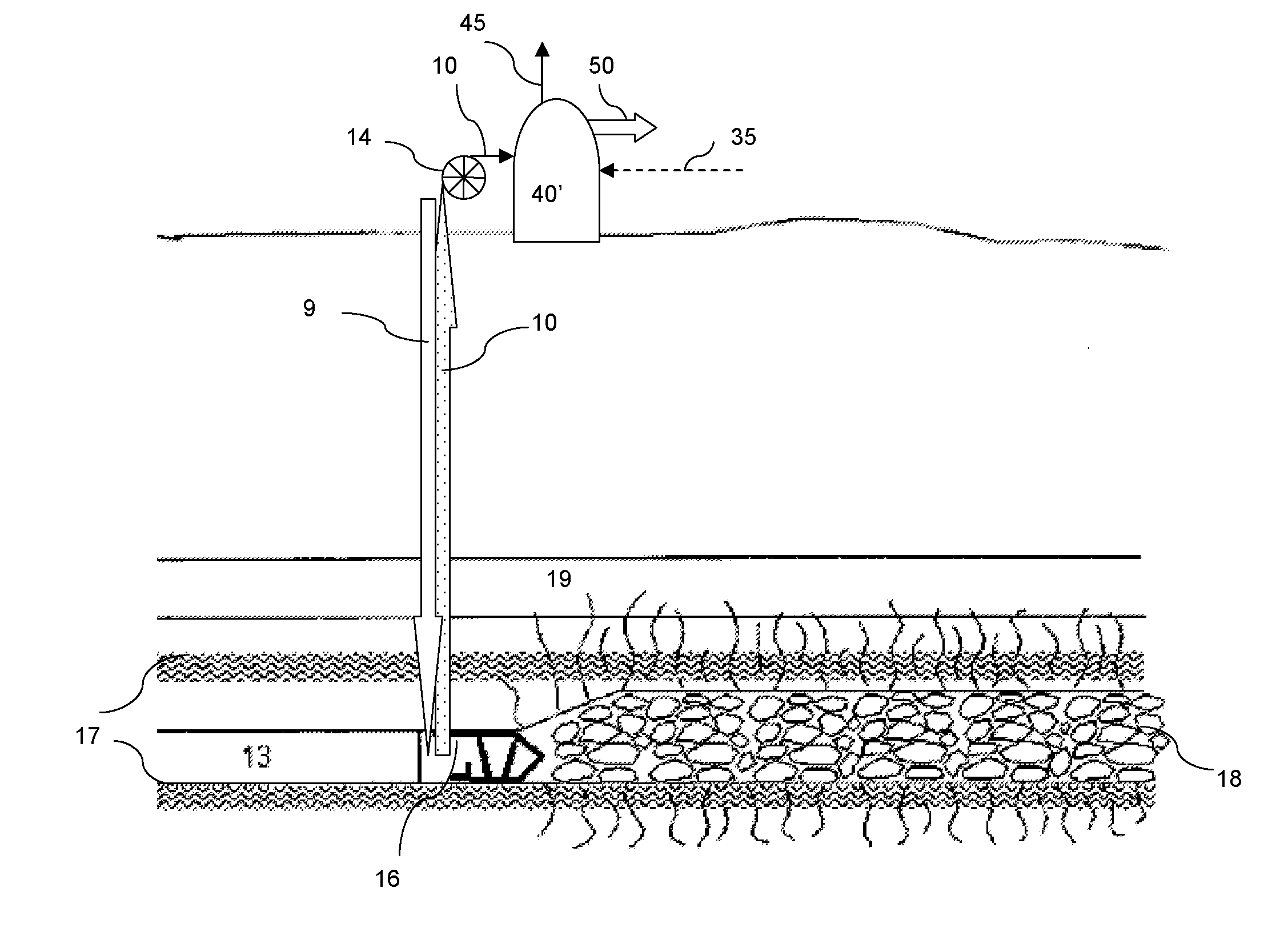
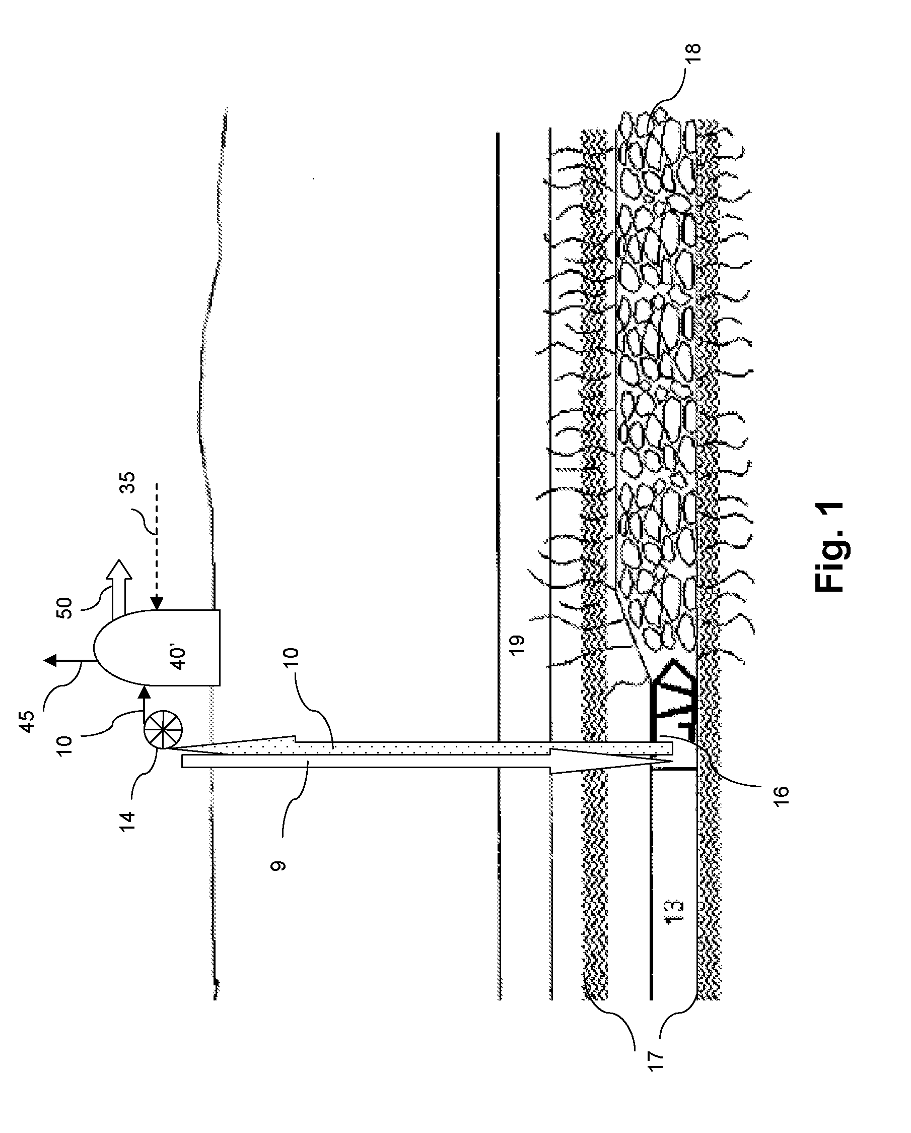
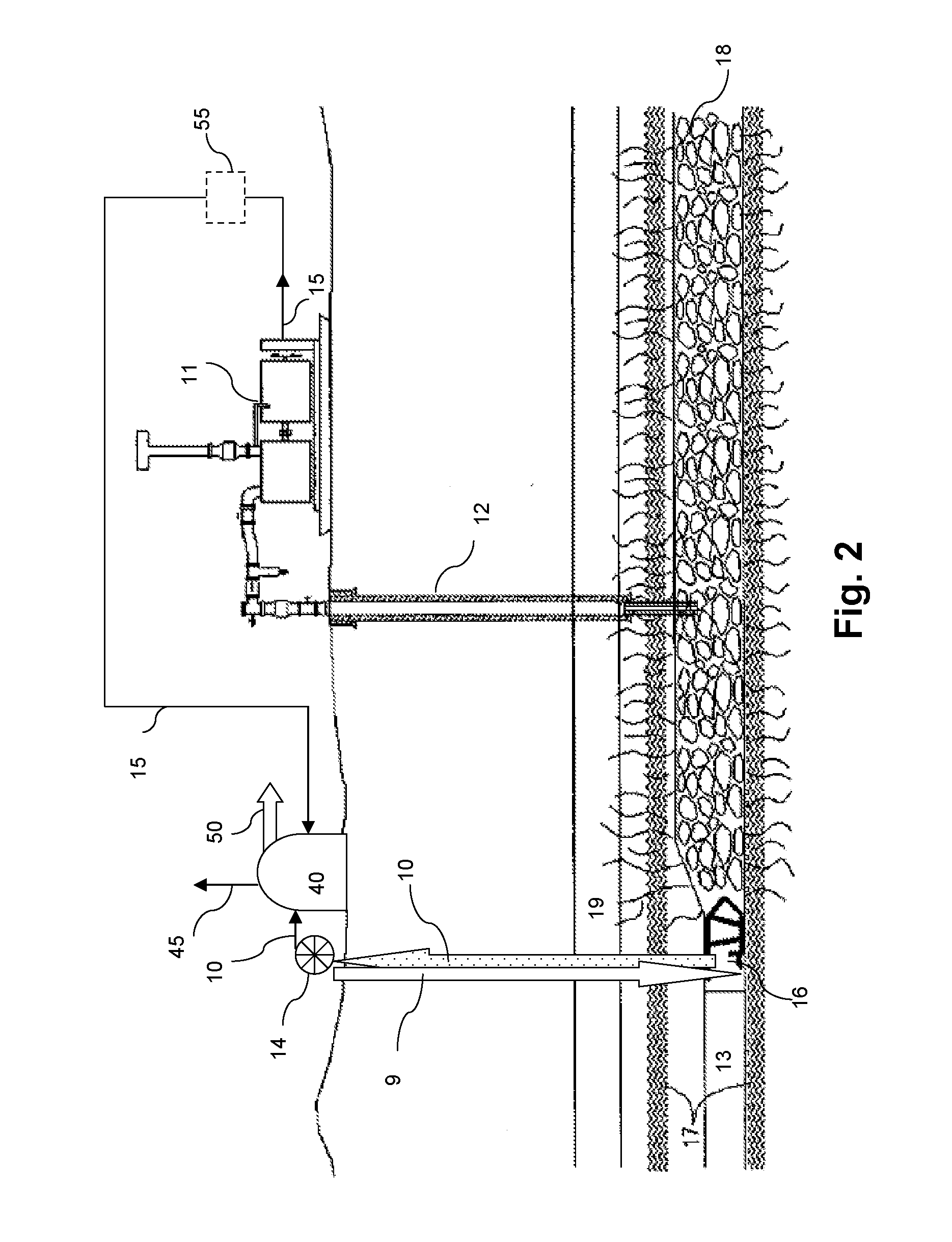
[0222]The method for utilization of VAM and gob gas may be exemplified as follows using a process flow scheme as illustrated in FIG. 4. VAM (stream 10) with an energetic flow of 1.2 trillions Btu per year, a gob gas (stream 15) with an energetic flow of 0.8 trillion Btu per year, and a purchased natural gas (stream 35) with an energetic flow of 1.7 trillion Btu per year are directed to a 45-Megawatt co-generation unit (40) to produce the following energetic output (50): about 400,000 MWH of electricity and about 154,000 pounds / hour of steam. It is expected that the reduction in greenhouse gas emissions will be about 55% less with the utilization of VAM and the gob gas in the co-generation plant.

[0223]This disclosure of all patent applications, and publications cited herein are hereby incorporated by reference, to the extent that they provide exemplary, procedural or other details supplementary to those set forth herein.

[0224]Should the disclosure of any of the patents, patent applic...


PUM


Abstract

Utilization of mine methane produced by mining a non-combustible ore, such as trona, as an energy source for heat, steam, and/or power generation. Such utilization is beneficial for a surface appliance which is close to surface outlet(s) of mine methane recovery system(s). A method for reducing greenhouse gas emissions generated during mining of a non-combustible ore uses the combustion of co-produced mine methane. The mine methane is recovered in a mine ventilation air exhaust with very low methane content and may be additionally recovered in a drainage gas, such as gob gas, with much higher methane content. The surface appliance may be selected from the group consisting of calciner, dryer, boiler, kiln, furnace, engine, turbine, power generation unit, co-generation unit, and any combinations thereof. Benefits may include reduction in energy purchases, reduction in greenhouse emissions, and/or gain through sale of carbon credits to the carbon market by registering carbon reductions.

Description

CROSS-REFERENCE TO RELATED APPLICATIONS[0001]The present application claims priority benefit to U.S. provisional application No. 61 / 475,905, filed on Apr. 15, 2011, the whole content (including drawings) of this application being herein incorporated by reference for all purposes.STATEMENT REGARDING FEDERALLY SPONSORED RESEARCH OR DEVELOPMENT[0002]Not applicable.TECHNICAL FIELD OF THE INVENTION[0003]The invention relates to a method for using mine methane exhausted during the mining of non-combustible ore as an energy source and / or combustion air in a surface refinery which processes the mined ore close to the mining operation. The invention particularly relates to a method for reducing greenhouse gas emissions caused during trona mining which employs ventilation air methane and optionally other methane-containing vent gases in the production of heat, steam, and / or electricity in one or more surface refinery appliances.BACKGROUND OF THE INVENTION[0004]During mining operations in an u...

Claims


Application Information

Patent Timeline
IPC IPC(8): F23L7/00
CPCF23G5/46F23G7/06E21F7/00Y02E20/12E21C41/20F23G2206/203
Inventor HUGHES, RONALDMORTIMER, BRYAN M.HANSEN, DAVID M.
Owner SOLVAY CHEM INC
Why Eureka
Try Eureka