Process for cogasifying and cofiring engineered fuel with coal

a technology of engineered fuel and cogasification, which is applied in the direction of solid fuel combustion, combustion types, lighting and heating apparatus, etc., can solve the problems of not being equipped with modern and advanced emission control technology, public health and environmental concerns, and the age of most us coal-fired power plants

Inactive Publication Date: 2012-10-25
REPOWER IP LLC
View PDF4 Cites 15 Cited by
  • Summary
  • Abstract
  • Description
  • Claims
  • Application Information

AI Technical Summary

Benefits of technology

[0016]In some embodiments, the first engineered fuel is different from the second engineered fuel. In some embodiments, the first engineered fuel is optimized for burning in a reducing environment, and the second engineered fuel is optimized for burning in an oxidizing environment. In some embodiments, the combustor is a boiler, and cofiring further comprises: combusting the second engineered fuel and the second fossil fuel in a combustion zone of the boiler, and combusting the syngas in a reburn zone of the boiler. In some embodiments, the cofiring step comprises one of direct cofiring and indirect cofiring.
[0017]In some embodiments, at least one of the first engineered fuel and the second engineered fuel comprises one or more sorbents. The one or more sorbents are selected from the group consisting of sodium sesquicarbonate (Trona), sodium bicarbonat

Problems solved by technology

Unfortunately, most US coal-fired power plants are over 40-50 years old, and are not equipped with modern and advanced emission control technologies such as flue gas desulfurization (FGD) for SOx removal and selective catalytic reduction (SCR) for NOx reduction.
As such, the air pollution emissions accompanying the coal combustion such as SOx, NOx, CO2, and particulates are significant, increasingly causing public health and environment concerns.
These post-combustion emission control technologies are expected to cost hundreds of millions of dollars to install and multimillions of dollars to operate and service every year.
Moreover, for power plants that use high sulfur coals, these technologies have an unintended side effect, i.e. making SO3 related corrosion and “blue plume” issues more prevalent.
Both methods are relatively inexpensive due to shared fuel processing, delivery and combustion equipments, but limited by the amount of biomass blend ratio to typically 5% for pulverized coal (PC) boiler and 10-20% for cyclone and fluidized bed boilers.
This third direct cofiring method has the advantage of better control over the biomass flow rate, and can achieve higher cofiring ratio (10% or higher for PC boilers, and 20% or higher for cyclone and fluidized bed units) than the previous two direct cofiring methods, but requires a separate feed line an

Method used


Image

  • Process for cogasifying and cofiring engineered fuel with coal
  • Process for cogasifying and cofiring engineered fuel with coal
  • Process for cogasifying and cofiring engineered fuel with coal

Examples


reference example 1

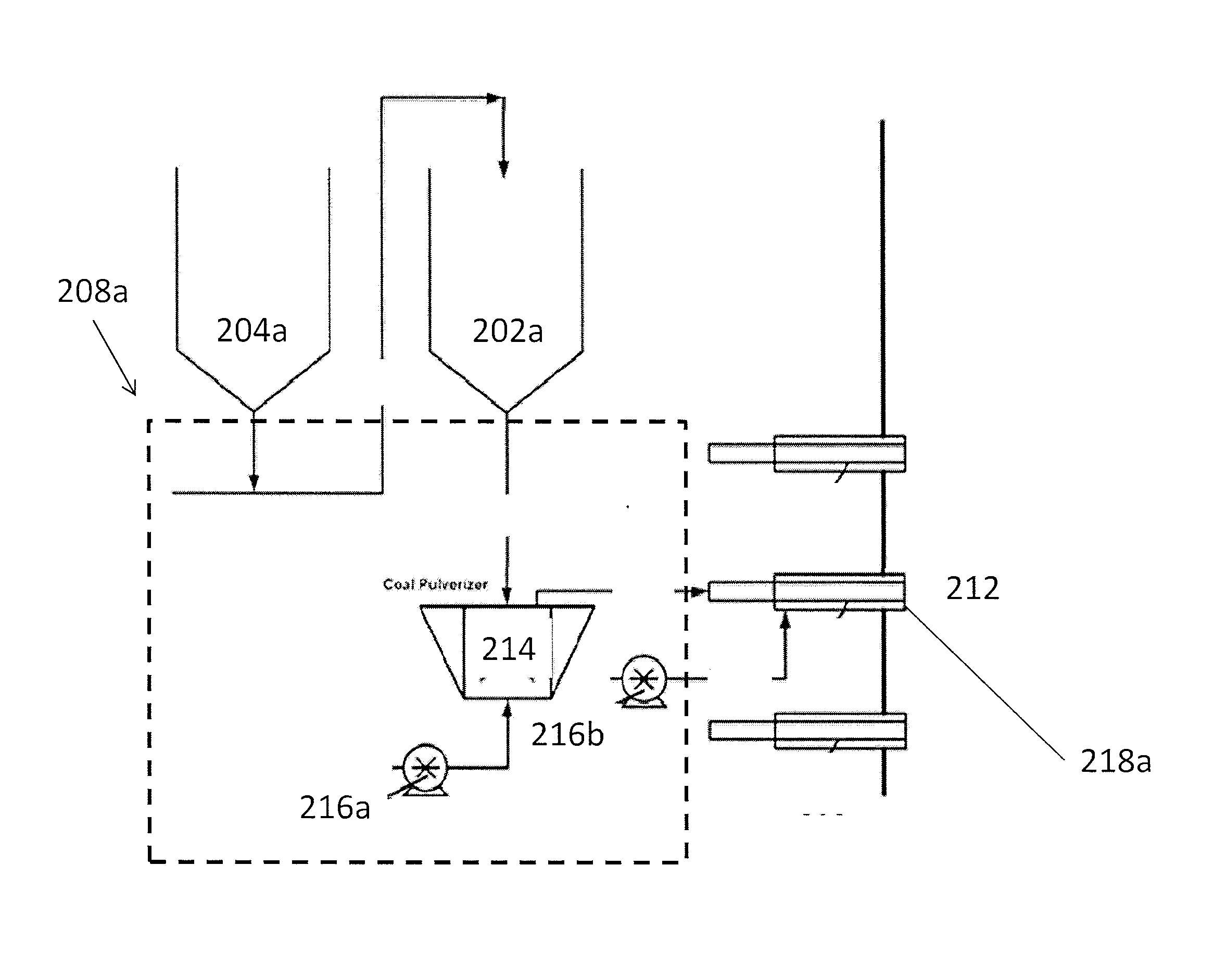
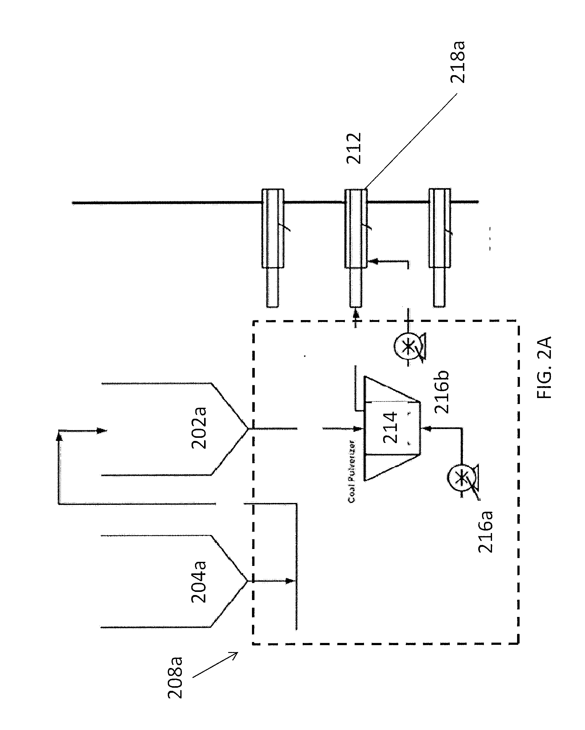
[0086]A computer process simulation is conducted using Aspen Plus V7.2 process simulation package. A coal having the characteristics listed in Table 1 (db: dry basis; ar: as received basis) is used. The engineered fuel can be formulated based on a typical waste residue composition in an advanced multi-material processing platform (MMPP) facility or traditional material recovery facility (MRF). The residue components are based on their weight composition with respect to paper, magazine, newsprint, cardboard, textile, plastics, woody biomass, yard trimmings and food scrap, etc. The engineered fuel is pelletized before chemical analysis. The analytical results are listed in Table 1 (column ‘EF’,). In all Examples below, the coal and EF feed rates are determined based on an assumed 400 MW power plant with an average heat rate of 9.478 MMBtu / MWh, with a total heat input rate of 7,582,400 MMBtu / hr. In all simulations, flue gas recycling technology is employed to control a constant flue ga...

example 1

[0087]This example establishes a baseline case in which 100% coal is combusted in a boiler. The coal feed rate is 296,475 lbs / hr. The simulation provided the following results (Table 2), with all concentration numbers corresponding to 7% O2 in the flue gas. Cl2 is given in ppb.

TABLE 2PollutantConcentration in Flue Gas, ppmEmission Rate, lbs / MMBtuNOx1580.205SO21,0372.850SO3540.186HCl490.077Cl21.23.51E−06

[0088]The simulation results demonstrate that:[0089]NOx emission potential level is high, and therefore requires NOx emission control technologies to be installed in the practical applications[0090]SO2 and HCl levels are significantly higher that the emission limits set up in the Clean Air Act1—(30 ppm for SO2 and 25 ppm for HCl, all corrected to 7% O2). Therefore, post combustion flue gas treatment, i.e. FGD, would be needed to meet such limits. Standards of Performance for Large Municipal Waste Combustors for Which Construction is Commenced After Sep. 20, 1994 or for Which Modificat...

example 2

[0094]In this example, coal is directly cofired with 5% engineered fuel (in heat basis) in a premixed manner. The coal feed rate is 281,651 lbs / hr and the engineered fuel feed rate is 23,771 lbs / hr. The engineered fuel contains sulfur and chlorine abatement sorbents with amounts calculated based on total sulfur and chlorine from both coal and the engineered fuel. As a result, the SO2, SO3, HCl and Cl2 concentrations in flue gas, or potential emission rates are reduced significantly compared to the above baseline case (Example 1), as shown in Table 3, with all concentration numbers corresponding to 7% O2 in flue gas, and Cl2 is given in ppb. With respect to NOx, there is only 2% reduction, likely because only 5% low fuel-nitrogen engineered fuel is cofired. Since Cl2 is substantially free, dioxins / furans formation will also be greatly reduced by cofiring the engineered fuel with coal.

[0095]Directly cofired engineered fuel containing about 5% of sorbents can substantially reduce the a...


PUM


Abstract

Described is an integrated process of cogasifying an engineered fuel, formulated to be suitable for working under reducing environment, with coal and cofiring another engineered fuel, formulated to be suitable for working under oxidizing environment, with coal to produce electric power.

Description

CROSS-REFERENCE TO RELATED APPLICATIONS[0001]This application claims priority to U.S. provisional application Ser. No. 61 / 478,089 filed on Apr. 22, 2011, the entirety of which is incorporated herein by reference.TECHNICAL FIELD[0002]The present invention generally relates to cofiring biomass or waste derived fuels with fossil fuels in commercial, industrial, and utility boilers.BACKGROUND[0003]As recently as 2009, the combustion of fossil fuels provided almost 70% of the electric power in the US, among which coal provided almost half of the total power generation. Given the unforeseeable uncertainty and often turbulence in oil-producing geopolitical areas, it is projected that coal, which has abundant reserves in the United States, would continue to be a dominant fuel for use in electricity generation in the US and other coal-rich regions. Unfortunately, most US coal-fired power plants are over 40-50 years old, and are not equipped with modern and advanced emission control technolog...

Claims


Application Information

Patent Timeline
IPC IPC(8): F23G5/027F23G5/14F23G7/00F23C1/00
CPCF23G5/027F23G2204/101F23G7/10F23G5/14F23G5/00F23G5/44F23G5/0276
Inventor BOHLIG, JAMES W.BAI, DINGRONG
Owner REPOWER IP LLC
Why Eureka
Try Eureka