Shielded flat ribbon cable and method for fabricating a shielded flat ribbon cable

Active Publication Date: 2012-10-25
HITACHI METALS LTD
View PDF15 Cites 13 Cited by
  • Summary
  • Abstract
  • Description
  • Claims
  • Application Information

AI Technical Summary

Benefits of technology

[0037]According to one embodiment of the invention, the gap formation-suppressing means is included, which prevents formation of gaps between the edge portions of the first shell and the edge portions of the second shell, respectively. The edge portions of the first shell and the edge portions of the second shell are then fixed together via the gap formation-suppressing means, and no gap exists between the edge portions of the first shell and the edge portions of the second shell, therefore ensuring excellent electromagnetic s

Problems solved by technology

Therefore, in this shielded flat ribbon cable, the variation in characteristic impedance tends to occur, and an impedance mismatch between the characteristic impedance and the load impedance tends to occur.
Accordingly, there is a problem in that this shielded

Method used


Image

  • Shielded flat ribbon cable and method for fabricating a shielded flat ribbon cable
  • Shielded flat ribbon cable and method for fabricating a shielded flat ribbon cable
  • Shielded flat ribbon cable and method for fabricating a shielded flat ribbon cable

Examples


first embodiment

[0051]Next, a first embodiment according to the invention will be explained in conjunction with the appended drawings.

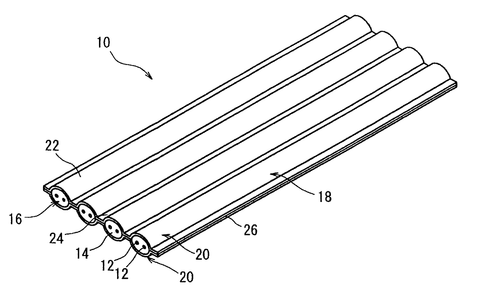
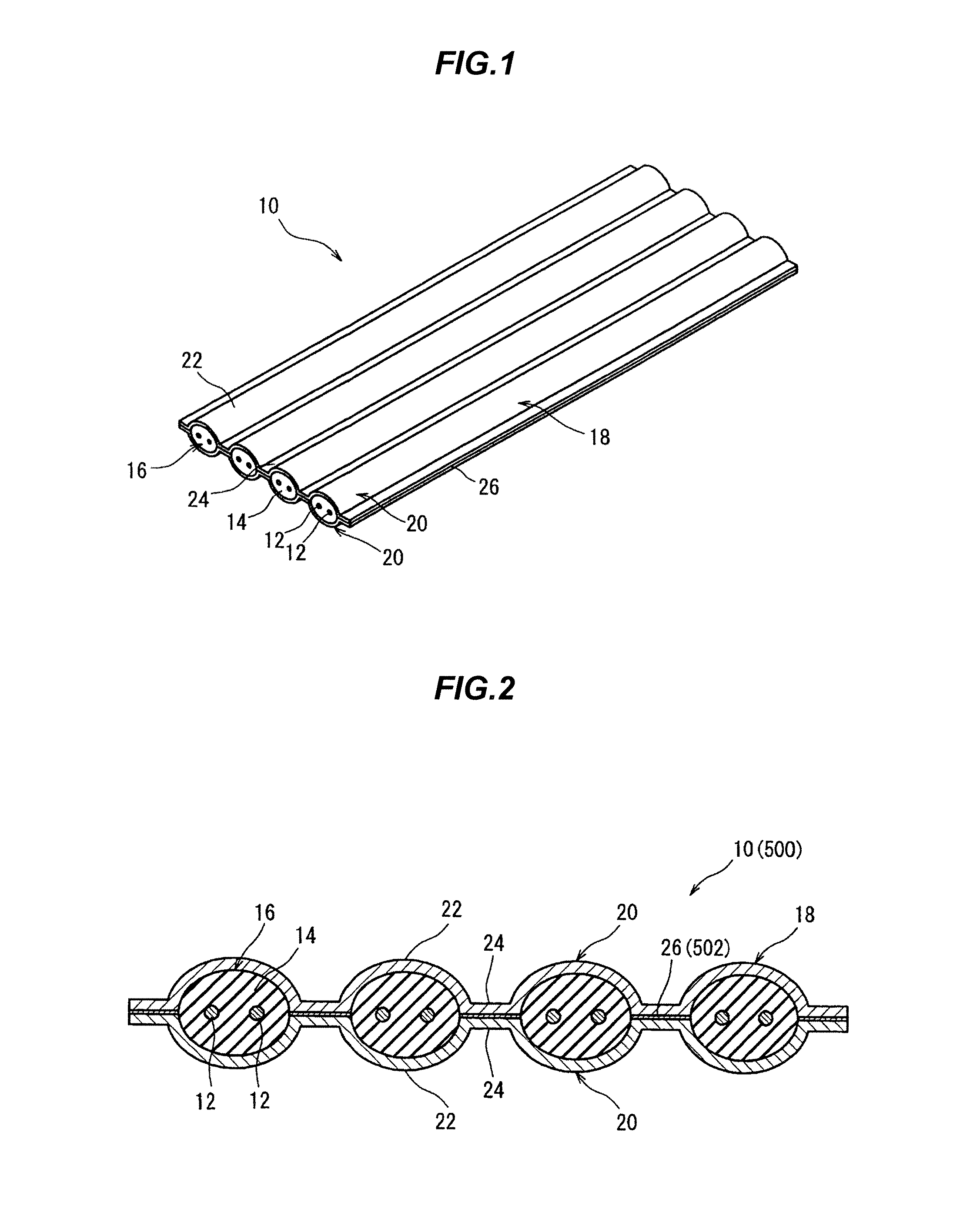
[0052]FIG. 1 is a schematic perspective view showing an appearance of a shielded flat ribbon cable 10 in the first embodiment, and FIG. 2 is a schematic transverse cross sectional view of the shielded flat ribbon cable 10.

[0053]The shielded flat ribbon cable 10 is used as a wiring member for e.g. relay devices such as switching hubs or media converters, information processing devices such as servers or personal computers, and the like. For example, the shielded flat ribbon cable 10 is used for connection between ICs (integrated circuits) mounted on a printed circuit board, or between an IC and an interface. The shielded flat ribbon cable 10 is especially suitable for 10 Gbps or more high speed signal transmission.

Shielded Flat Ribbon Cable 10

[0054]As shown in FIGS. 1 and 2, the shielded flat ribbon cable 10 has a plurality of inner conductors 12. The inner conductors...

second embodiment

[0078]Next, the second embodiment will be explained below. Incidentally, in the embodiments description below, elements the same as or similar to those of the preceding embodiment are given the same names or numerals, and detailed descriptions thereof are omitted.

Shielded Flat Ribbon Cable 100

[0079]FIG. 5 is a schematic perspective view showing an appearance of a shielded flat ribbon cable 100 in the second embodiment, and FIG. 6 is a schematic transverse cross sectional view of the shielded flat ribbon cable 100.

[0080]The shielded flat ribbon cable 100 differs from the shielded flat ribbon cable 10 in that it has no solder layers 26, but is further provided with caulking portions 104a and 104b in the edge portions 24.

[0081]The caulking portions 104a and 104b project from the edge portions 24 toward one side in a direction of superimposing two shells 102a and 102b. The caulking portions 104a have a V transverse cross section shape, and the caulking portions 104b have a substantially...

third embodiment

[0092]Next, the third embodiment will be explained below.

Shielded Flat Ribbon Cable 200

[0093]FIG. 7 is a schematic perspective view showing an appearance of a shielded flat ribbon cable 200 in the third embodiment, and FIG. 8 is a schematic transverse cross sectional view of the shielded flat ribbon cable 200.

[0094]The shielded flat ribbon cable 200 differs from the shielded flat ribbon cable 100 in that one shell 202b has caulking holes 204b in its edge portions 24 respectively, while an other shell 202a has caulking portions 204a which engage circumferential edges of the caulking holes 204b respectively.

[0095]More specifically, the edge portions 24 of one shell 202b are formed with a plurality of the caulking holes 204b respectively spaced apart in a longitudinal direction thereof. The other shell 202a is then provided with a plurality of the caulking portions 204a that are located in correspondence with the caulking holes 204b respectively.

[0096]The caulking portions 204a project...


PUM

PropertyMeasurementUnit
Electrical conductivityaaaaaaaaaa

Abstract

A shielded flat ribbon cable includes a plurality of insulated conductors being spaced parallel to each other, the insulated conductors each including an inner conductor and an insulation coating the inner conductor; an outer conductor bundling the insulated conductors together, the outer conductor including a first shell and a second shell in association with each other to sandwich the insulated conductors therebetween, each of the first shell and the second shell including a plurality of grooves covering outer surfaces of the insulated conductors, and a plurality of edge portions integral with both sides of the grooves, and gap formation-suppressing means for suppressing formation of gaps between the edge portions of the first shell and the edge portions of the second shell, respectively.

Description

[0001]The present application is based on Japanese patent application No. 2011-094716 filed on Apr. 21, 2011 the entire contents of which are incorporated herein by reference.BACKGROUND OF THE INVENTION[0002]1. Field of the Invention[0003]This invention relates to a shielded flat ribbon cable and a method for fabricating a shielded flat ribbon cable.[0004]2. Description of the Related Art[0005]Shielded flat ribbon cables are used within electronic equipment as wiring. For example, Japanese Utility Model Laid-Open No. 63-127018 (JP-U 63-127018) discloses a shielded flat ribbon cable having a plurality of insulated wires comprising conductors and insulations coating the conductors respectively, in which the insulated wires are covered pair by pair with an individual shield layer and an electrically conductive polymeric resin. The pair of the insulated wires, the individual shield layer and the electrically conductive polymeric resin constitute an inner sheathed wire, and a plurality o...

Claims


Application Information

Patent Timeline
IPC IPC(8): H05K9/00H01R43/00
CPCH01B7/0861Y10T29/49194H01B11/203
Inventor SUNAGA, YOSHINORISUGIYAMA, TAKAHIRO
Owner HITACHI METALS LTD
Why Eureka
Try Eureka