Heatable gas sensor and method for the production thereof

a gas sensor and heat sink technology, applied in the direction of gas analyzer construction details, instruments, electrical equipment, etc., can solve the problems of complex and expensive production, insufficient sensitivity of the sensor, and limited use of the entire gas sensor, etc., and achieve the effect of being especially simple to produ

Inactive Publication Date: 2012-11-01
WIESNER MANFRED +1
View PDF19 Cites 6 Cited by
  • Summary
  • Abstract
  • Description
  • Claims
  • Application Information

AI Technical Summary

Benefits of technology

[0022]Production of such a sensor is also simpler and less expensive because no processing of the substrate is necessary nor is a housing necessary.
[0023]The combined use of the electrical elements for heating and for measurement yields a heating effect directly at the measurement site and simplifies the design and production because a separate heating need not be provided. Thus an embedded element may be used for heating, and another element which is also embedded may be used for measuring the current or voltage in the meantime.
[0024]Finally, sintering the metal oxide increases both the mechanical stability and the signal stability of the gas sensor. The sensor signal also remains stable over a long term regardless of the mechanical influences acting from the outside.
[0026]Expediently at least one of the elements for heating the metal oxide can carry electricity. The element can therefore carry a heating current which results in heating due to the resistance of the electrical element. This heating occurs directly in the area of the metal oxide which is located next to the element. In this way the spatial area of the porous metal oxide in which the change in conductivity is measured can be heated directly. No foreign bodies such as substrates or heating element carriers are present and therefore need not be heated and they also do not limit the spatial measurement area. The result is a good thermal stability. Since the measurement result depends to a great extent on the temperature of the metal oxide, this also results in an improvement in the stability of the measurement.
[0035]Production is especially simple when at least the metal oxide powder is introduced into a mold and the electrical elements are placed on the layer of metal oxide powder with a distance between them. The elements may then be covered with another layer of metal oxide and sent for the sintering process.
[0036]To be able to control the distance between the elements, according to another embodiment of the invention it is possible to first introduce metal oxide powder into a mold, then apply an element, for example, in a meandering form, to the metal oxide powder, to cover the element with a layer of metal oxide powder, to apply another element, for example, also in a meandering form, and to also cover this with metal oxide powder before sintering.

Problems solved by technology

Therefore the entire gas sensor is limited to use purposes in which the gas to be monitored has a sufficiently high temperature.
Due to the design of the electrical elements for heating the metal oxide on one side of a substrate and for measuring a conductivity of the metal oxide on the opposite side of the substrate, this yields disadvantages with the gas sensor known from EP 0 464 244 B1.
Thus, on the one hand, production is complex and expensive but on the other hand, the heating energy does not act directly on the metal oxide surrounding the electrical elements for measuring the metal oxide but instead acts through the substrate.
Finally, the sensitivity of the sensor is not optimal because there is only a limited amount of metal oxide between the electrical measurements for measuring the metal oxide and the sensor is gas-sensitive on only one side.
Under typical use conditions, the sensors are exposed to high temperatures up to 1200° C., mechanical stresses in the form of vibrations and thermal stresses due to extreme temperature changes and must also be able to withstand chemical influences due to reducing and corrosive gas components over long periods of time without undergoing any significant aging, so there are weaknesses in principle with the known substrate-based sensors, which must be compensated by increased technical complexity.
In vaporization of the passivation layer due to the aforementioned adverse operating conditions, there are negative effects on the sensitivity of the gas sensor.
Furthermore, the substrate may be excited to vibrations, and thermal stresses may lead to damage to the electrical elements on the substrate.
Finally, production of a substrate-based gas sensor such as that known from the DE 44 28 155 C2 or EP 0 464 144 B1 is technically complex and expensive because special equipment is required to form small structures on a substrate.
Although U.S. Pat. No. 3,835,529 describes a substrate-free gas sensor based on an inorganic metal oxide semiconductor, no heating element is provided in the substrate-free embodiment to heat the metal oxide.
This leads to the disadvantages mentioned above.
The gas-impermeable housing reduces the sensitivity of the sensor because gas cannot reach the sensor on all sides and instead the gas must flow through end caps to the sensor.
Furthermore, heating of the gas sensor results in unfavorable inherent thermal conditions.
Finally, the loose packing of the metal oxide has a negative effect on the signal stability because mechanical stresses such as vibrations interfere with the contact structure.
This is fundamentally problematical because there may be faulty flows.
Furthermore, the thermistor does not have porous material and the gas sensor is not sensitive on all sides.

Method used


Image

  • Heatable gas sensor and method for the production thereof
  • Heatable gas sensor and method for the production thereof
  • Heatable gas sensor and method for the production thereof

Examples


Embodiment Construction

[0016]This object is achieved by a heatable gas sensor and a method of manufacturing same having the features of claim 1 and / or 6.

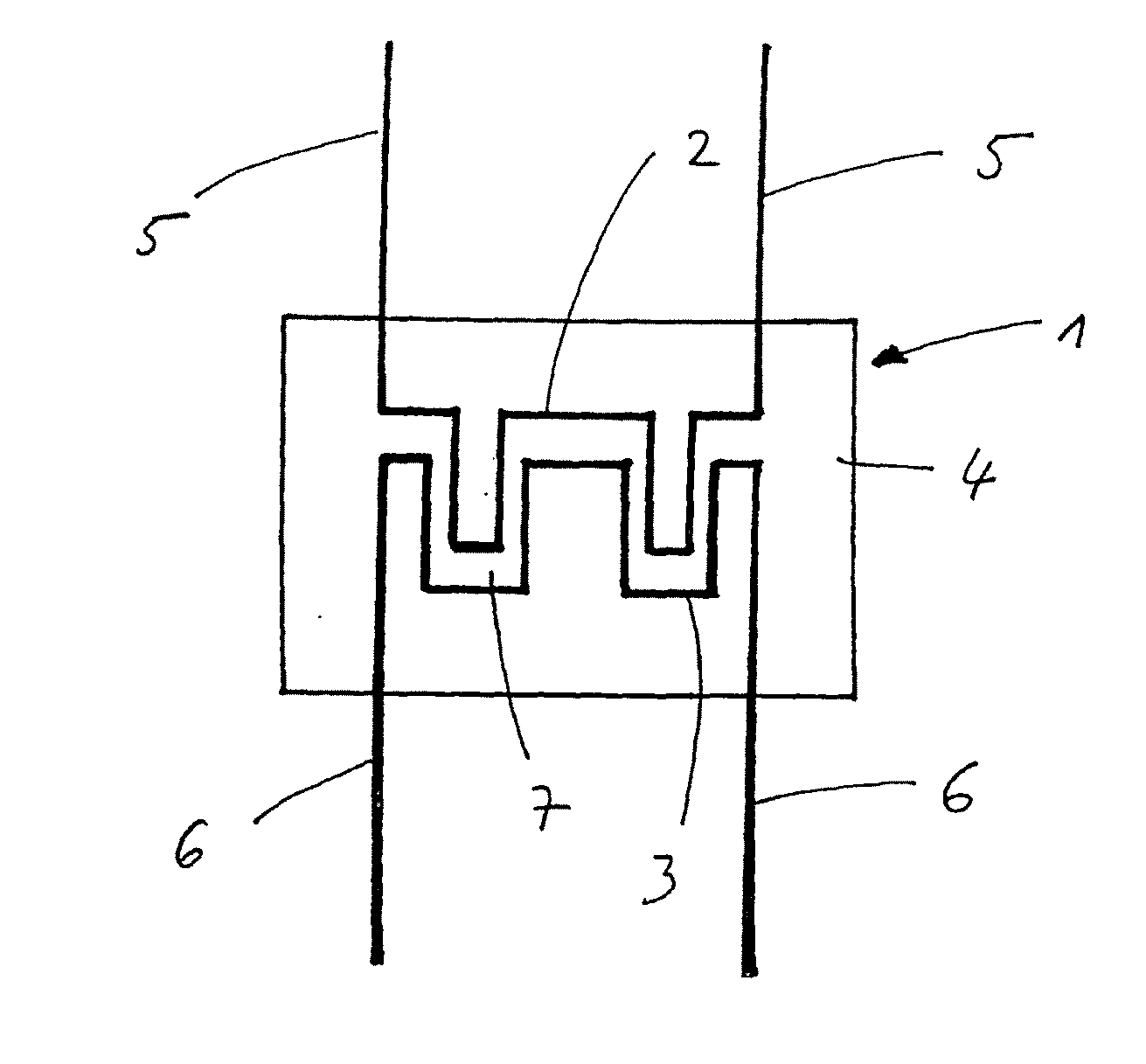
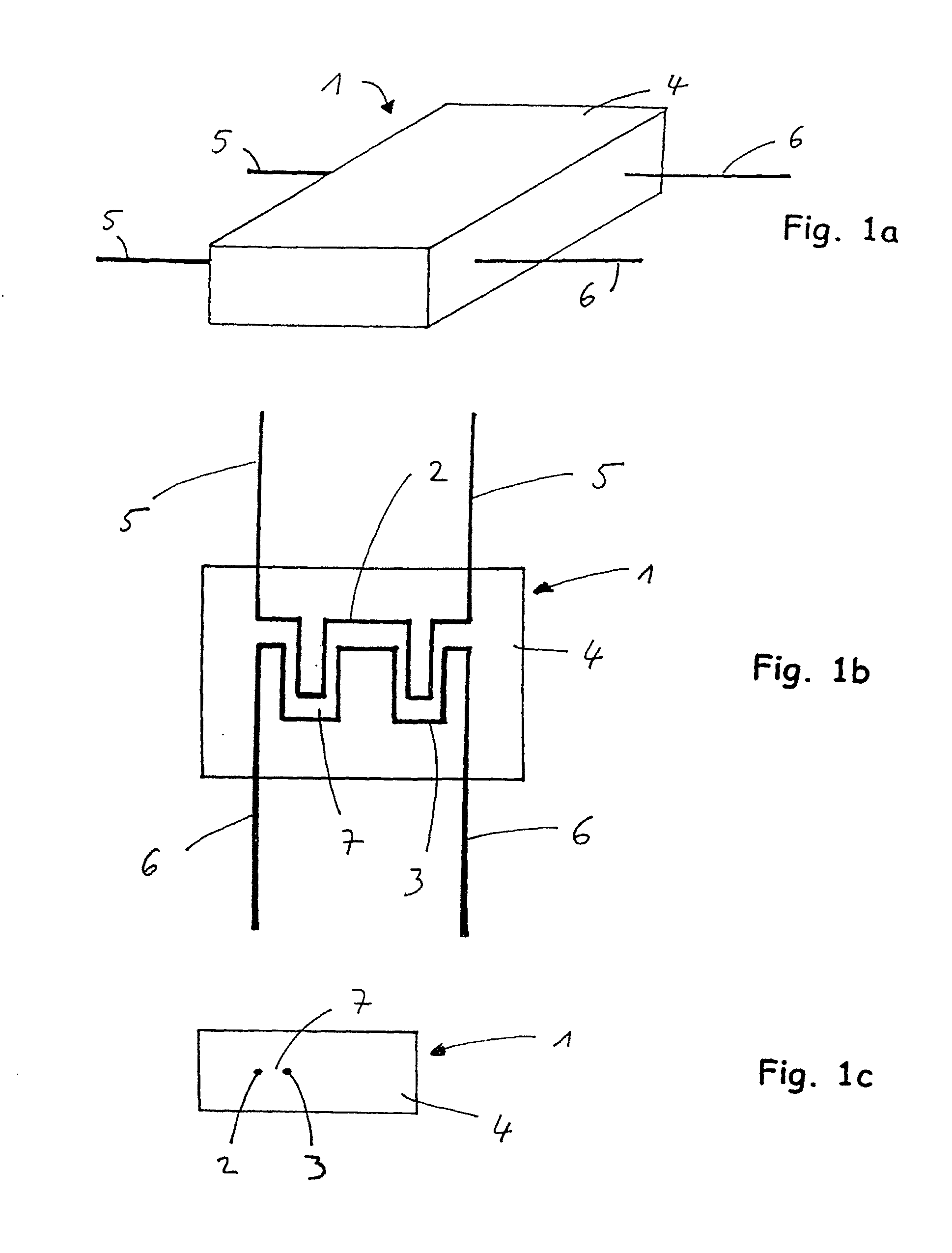
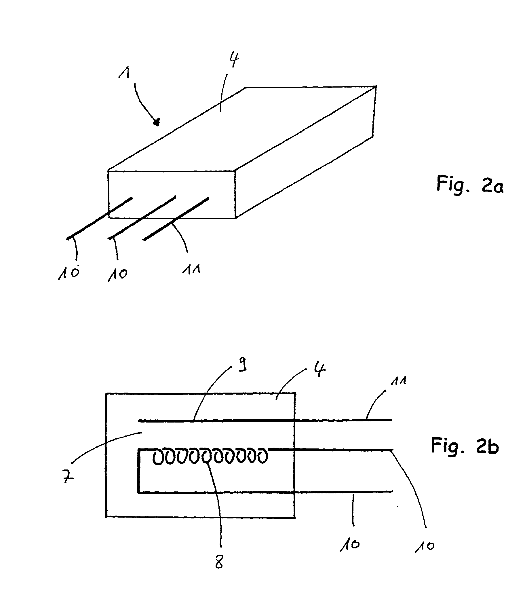
[0017]Accordingly, a heatable gas sensor for gases which contain reducing substances such as methane, ethane, propane, carbon monoxide, hydrogen and / or the like, with a gas-sensitive porous metal oxide and electrical elements spaced a distance apart from one another, is created for heating the metal oxide and for measuring the conductivity of the metal oxide, in which the elements are each embedded in sintered metal oxide.

[0018]The gas sensor according to the invention is thus free of a substrate, and the sintered metal oxide surrounds the electrical elements on all sides.

[0019]Therefore, this first yields an increased sensitivity because the conductivity is measured in a three-dimensional spatial area along and between the electrical elements, such that this area offers a much larger internal surface of the porous metal oxide, in comparison with the know...


PUM

PropertyMeasurementUnit
temperaturesaaaaaaaaaa
temperatureaaaaaaaaaa

Abstract

The invention relates to a heatable gas sensor (1) for gases containing reducing substances, comprising a gas-sensitive porous metal oxide (4) and electrical elements (2, 3, 8, 9, 14, 15, 16, 18) spaced apart from one another both for heating the metal oxide (4) and for measuring a conductivity of the metal oxide (4), wherein each electrical element (2, 3, 8, 9, 14, 15, 16, 18) is spatially embedded in the metal oxide (4). The invention further relates to a method for producing the gas sensor.

Description

FIELD OF THE INVENTION[0001]The invention relates to a heatable gas sensor and a method for producing the same according to the preamble of claim 1 and / or 6.TECHNICAL BACKGROUND[0002]For detection and optional determination of the concentration of substances such as methane, ethane, propane, carbon monoxide, hydrogen, etc. in gas mixtures, heating gases, exhaust gases and / or the like, gas sensors based on inorganic metal oxide semiconductors (MOX) are known from the state of the art. When such gas sensors, which are designed as a porous solid, come in contact with the aforementioned substances or other reducing substances, the conductivity of the metal oxide changes at least at its surface. The change in conductivity of the metal oxide can be detected and analyzed by means of an electronic unit to detect reducing substances and optionally determine their concentration.[0003]Such a gas sensor is known from DE 44 28 155 C2. The gas sensor comprises a substrate on which an interdigital...

Claims


Application Information

Patent Timeline
Patent Type & Authority Applications(United States)
IPC IPC(8): G01N27/12H05K13/00
CPCG01N27/12Y10T29/49117G01N33/005G01N33/004
Inventor WIESNER, MANFREDKECHTER, ANDREAS
Owner WIESNER MANFRED
Why Eureka
Try Eureka