Laser processing systems and methods for beam dithering and skiving

a laser processing and beam technology, applied in the field of laser processing, can solve the problems of reducing the processing time affecting the processing efficiency of laser processing machines, and requiring high beam position acceleration, so as to reduce the amount of processing time and variable width of the trench

Active Publication Date: 2012-11-01
ELECTRO SCI IND INC
View PDF28 Cites 43 Cited by
  • Summary
  • Abstract
  • Description
  • Claims
  • Application Information

AI Technical Summary

Benefits of technology

[0014]In another embodiment, a method for dithering a laser beam creates a trench in a workpiece. The method includes imparting first relative movement of a laser beam path along a beam trajectory defining a length of the trench with respect to a surface of the workpiece, and imparting a second relative movement of the laser beam path along a plurality of dither rows. The second relative movement is superimposed on the first relative movement to widen the trench. A width of the trench is variable. The me

Problems solved by technology

These optical systems may have significant time delays (e.g., about 10 milliseconds (ms) to about 10 s) when changing laser processing spot characteristics.
Other problems are associated with building a machine to meet the processing parameters noted above.
When processing traces at high velocity, the variation in trajectory angle may require high beam position acceleration at very short time scales.
Such accelerations and/or velocities may be difficult to achieve in traditional laser processing machines, which have relied on beam positionin

Method used


Image

  • Laser processing systems and methods for beam dithering and skiving
  • Laser processing systems and methods for beam dithering and skiving
  • Laser processing systems and methods for beam dithering and skiving

Examples


Embodiment Construction

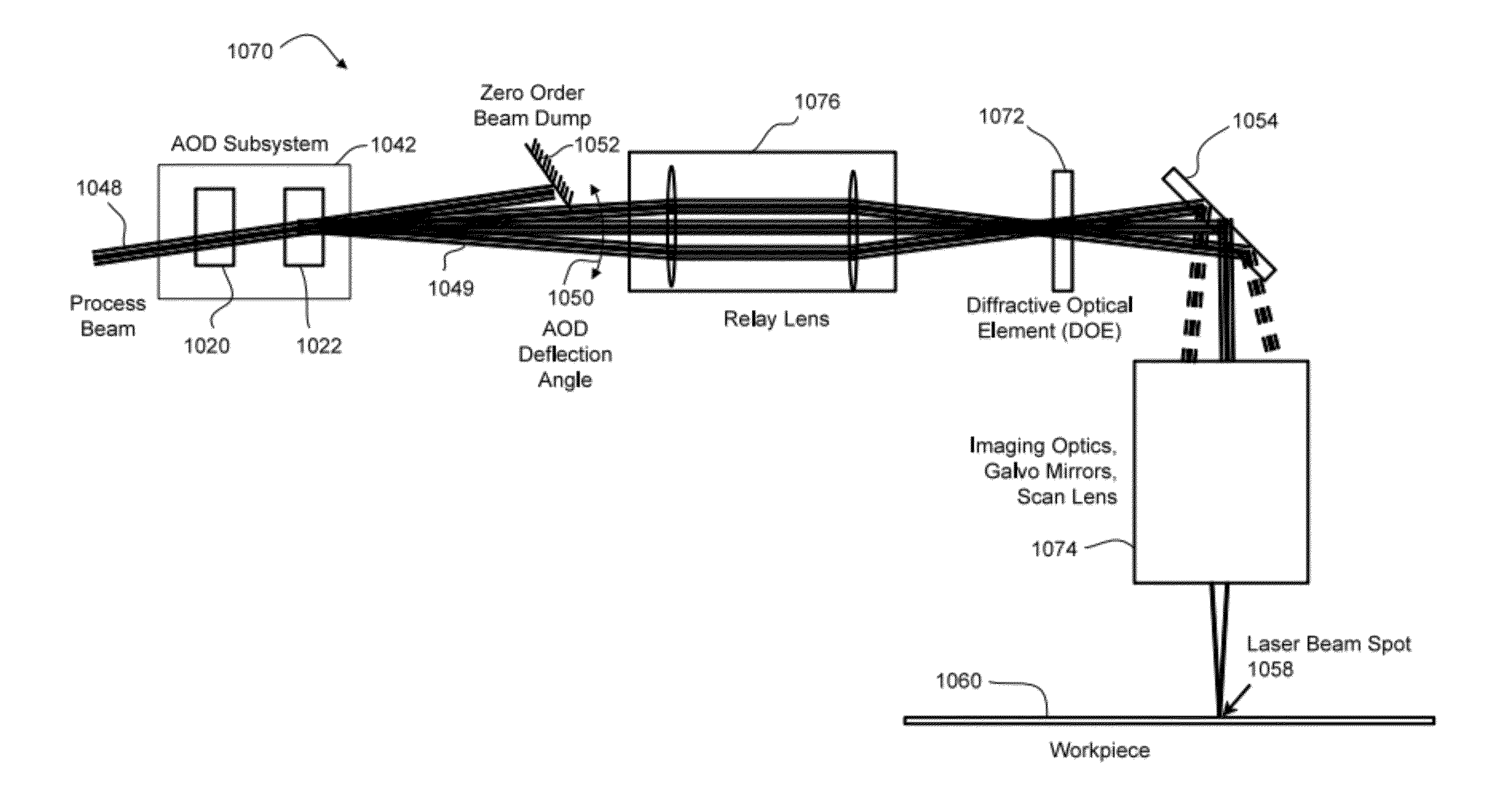
[0072]The disclosure contained herein describes implementation details for an LDA system using acousto-optic deflectors (AODs) as a beam positioning device. While the example embodiments disclosed herein are directed to AODs, electro-optic deflectors (EODs) may also be used. In certain embodiments, for example, EODs are suitable replacements for some or all AOD pointing (deflection) functions.

[0073]In certain embodiments, the geometry of processed features (e.g., width and depth) may be specified at a high level by the user, and then translated into process commands by machine control software. Laser power and details of the dithering operation are automated in certain embodiments to prevent a burdensome, error-prone manual machine setup process. For example, a user may be provided a simple process to create geometric features with nominal dimensions. The features may include trenches with a target width and depth, or pads with a target diameter and depth. The user may directly ente...


PUM

PropertyMeasurementUnit
Angleaaaaaaaaaa
Poweraaaaaaaaaa
Radiusaaaaaaaaaa

Abstract

A laser processing system includes a first positioning system for imparting first relative movement of a beam path along a beam trajectory with respect to a workpiece, a processor for determining a second relative movement of the beam path along a plurality of dither rows, a second positioning system for imparting the second relative movement, and a laser source for emitting laser beam pulses. The system may compensate for changes in processing velocity to maintain dither rows at a predetermined angle. For example, the dither rows may remain perpendicular to the beam trajectory regardless of processing velocity. The processing velocity may be adjusted to process for an integral number of dither rows to complete a trench. A number of dither points in each row may be selected based on a width of the trench. Fluence may be normalized by adjusting for changes to processing velocity and trench width.

Description

RELATED APPLICATION[0001]This application claims the benefit under 35 U.S.C. §119(e) of U.S. Provisional Application No. 61 / 406,038, filed Oct. 22, 2010, which is hereby incorporated by reference herein in its entirety.TECHNICAL FIELD[0002]This disclosure is related to laser processing of dielectric or other materials.BACKGROUND INFORMATION[0003]Laser processing of dielectric and conductive materials is commonly used to ablate fine features in electronic components. For example, chip packaging substrates may be laser processed in order to route signals from the semiconductor die to a ball-grid array or similar package. Laser processed features may include signal traces, ground traces, and microvias (to connect signal traces between package layers).[0004]Laser direct ablation (LDA) incorporates signal and ground traces on a single layer to tightly control signal impedance while reducing the number of layers in a chip package. Such an approach may require small feature dimensions and ...

Claims


Application Information

Patent Timeline
IPC IPC(8): B23K26/073B29C59/16
CPCB23K26/0639B23K2201/40B23K26/063H01L21/4853B23K26/0732B23K26/0807B23K26/367B23K26/364B23K26/08G06F2113/18G06F30/39B23K26/064B23K26/082B23K26/0622B23K2101/40B23K26/0643
Inventor UNRATH, MARK A.BERWICK, ANDREWMYACHIN, ALEXANDER A.
Owner ELECTRO SCI IND INC
Why Eureka
Try Eureka