Method for manufacturing vane

Inactive Publication Date: 2012-11-08
IHI CORP
View PDF2 Cites 15 Cited by
  • Summary
  • Abstract
  • Description
  • Claims
  • Application Information

AI Technical Summary

Benefits of technology

[0008]An object of the present invention is to provide a method for manufacturing a vane that can improve turbine efficiency by reducing thickness of a trailing edge of the vane.
[0014]According to the above aspects, since a portion from a leading edge to an intermediate position in the vane made of composite material can be made thick and a portion from the intermediate position to a trailing edge can be made thin, rigidity of the vane made of composite material can be secured and also the trailing edge of the vane can be made thin. As a result, since pressure loss near the trailing edge of the vane can be restricted, turbine efficiency or compressor efficiency can be improved.

Problems solved by technology

As a result, pressure loss increases and thereby it becomes difficult to improve turbine efficiency.
Note that this issue occurs not only in a turbine vane made of composite material used in a turbine of a gas turbine engine but also in a compressor vane (including a compressor stator vane and a compressor rotor blade) made of composite material used in a gas turbine compressor.

Method used


Image

  • Method for manufacturing vane
  • Method for manufacturing vane
  • Method for manufacturing vane

Examples


first embodiment

[0052]A method for manufacturing a turbine stator vane according to a first embodiment will be explained with reference to a flow chart shown in FIG. 4 and FIGS. 5(a) to 7(b).

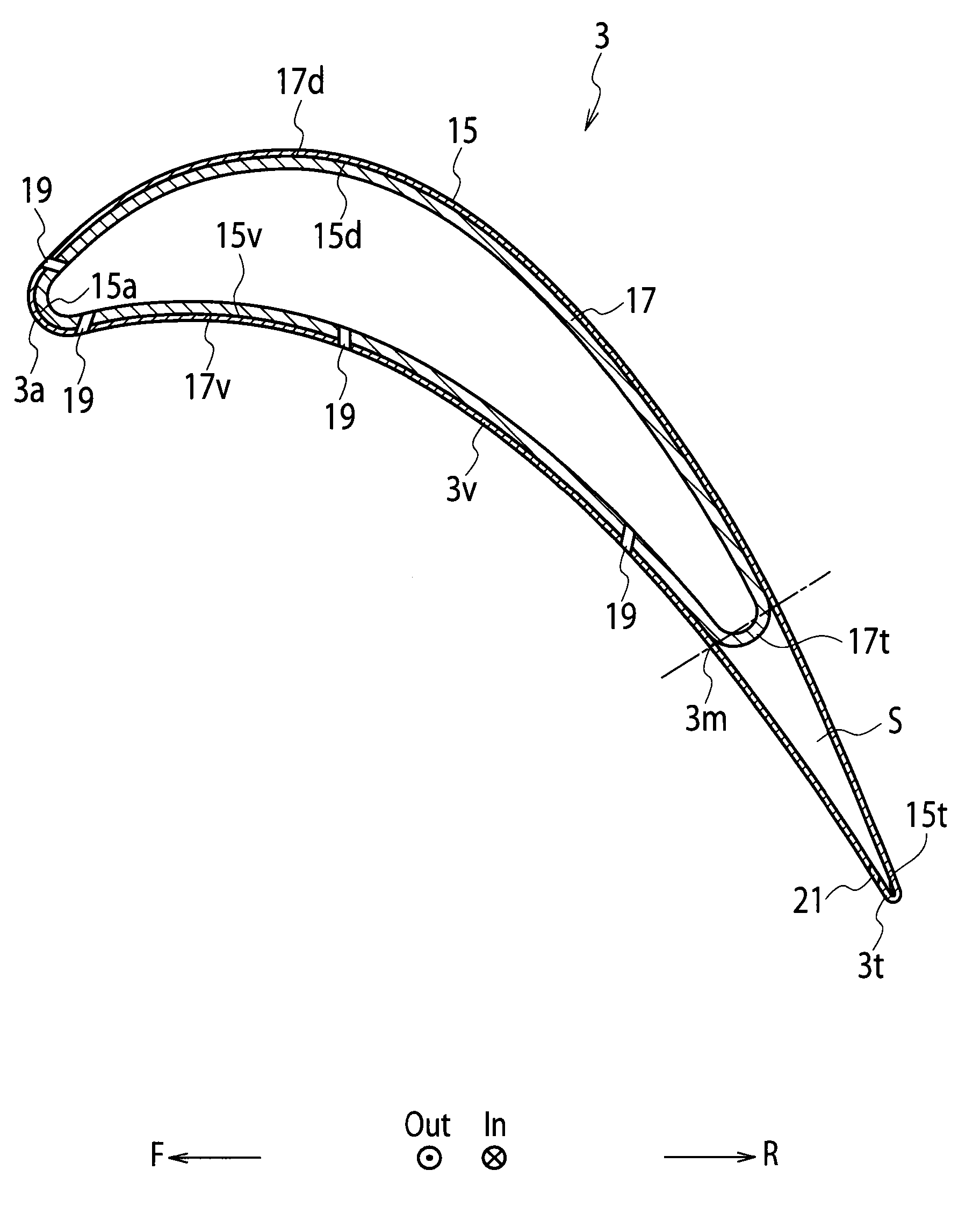
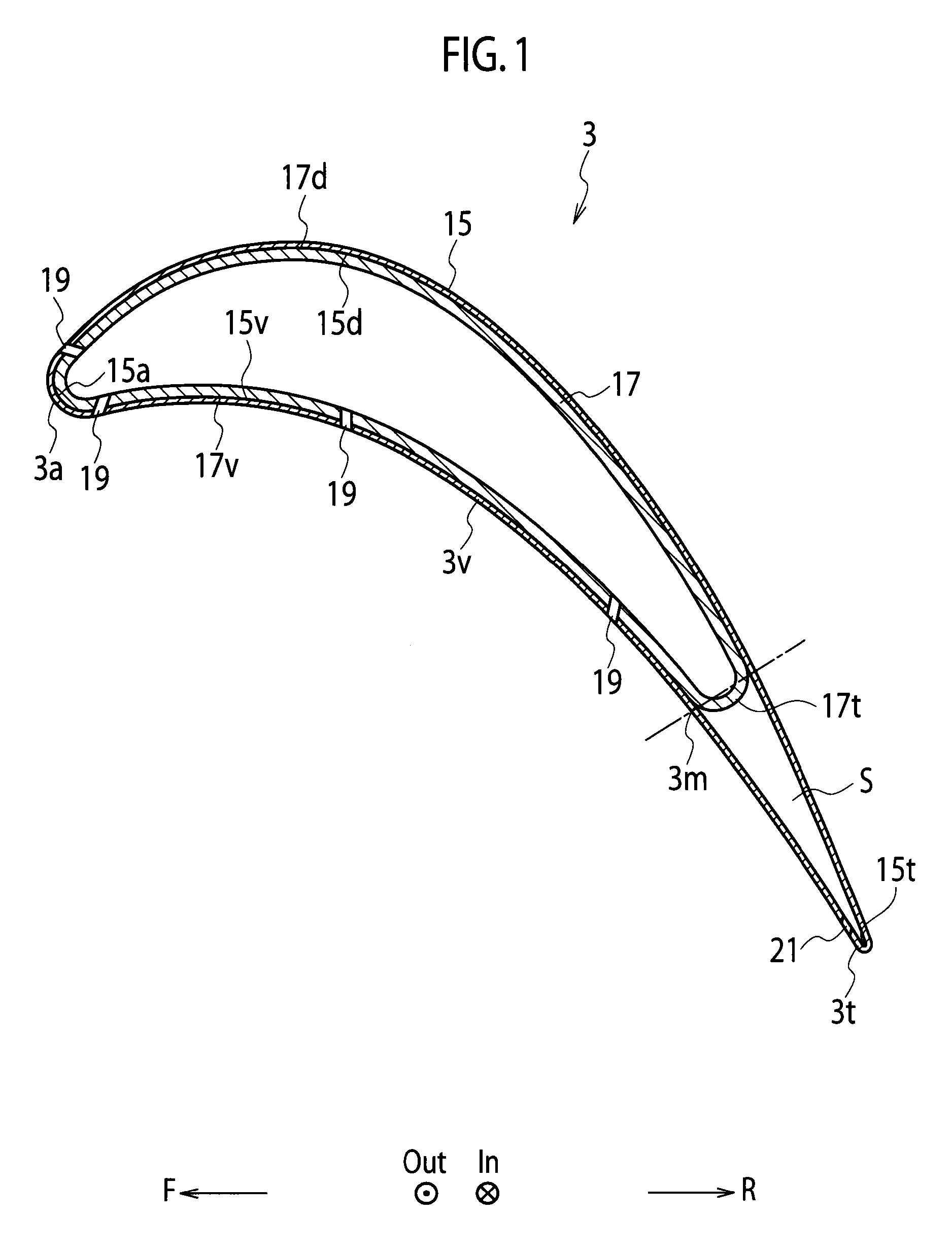
[0053]The method for manufacturing a turbine stator vane according to the present embodiment is a method for manufacturing the turbine stator vane 3 shown in FIG. 1. The present method includes an inner ply vane woven-fiber forming process, an inner ply vane infiltration process, a jig removal process, an integrating process, an outer ply vane woven-fiber forming process, an outer ply vane infiltration process, a supplemental jig removal process, and a machining process. Then, specific workings in the processes in the manufacturing method according to the present embodiment are presented as follows.

(Step S11) Inner Ply Vane Woven-Fiber Forming Process

[0054]As shown in FIG. 5(a), using a jig 31 that has a surface profile corresponding to an inner surface profile of the inner ply vane 17, ceramic fiber (fiber bun...

second embodiment

[0066]A method for manufacturing a turbine stator vane according to a second embodiment will be explained with reference to a flow chart shown in FIG. 8, FIG. 5(a) and FIGS. 9(a) to 10(b).

[0067]The method for manufacturing a turbine stator vane according to the present embodiment is a method for manufacturing the turbine stator vane 3 shown in FIG. 1. The present method includes an inner ply vane woven-fiber forming process, an integrating process, an outer ply vane woven-fiber forming process, an infiltration process, a removal process, and a machining process. Then, specific workings in the processes in the manufacturing method according to the present embodiment are presented as follows.

(Step S21) Inner ply Vane Woven-Fiber Forming Process

[0068]As shown in FIG. 5(a), by carrying out a process similar to the inner ply vane woven-fiber forming process (step S11) in the first embodiment, an inner ply vane woven-fiber formed body 17F constituted of ceramic fiber is formed on a surfac...

third embodiment

[0078]A method for manufacturing a turbine stator vane according to a third embodiment will be explained with reference to a flow chart shown in FIG. 11, FIGS. 5(a) to (c) , FIGS. 12 (a) to 13 and FIG. 16(b).

[0079]The method for manufacturing a turbine stator vane according to the present embodiment is a method for manufacturing the turbine stator vane 23 shown in FIG. 3. The present method includes an inner ply vane woven-fiber forming process, an inner ply vane infiltration process, an integrating process, an outer ply vane woven-fiber forming process, an outer ply vane infiltration process, a jig removal process, and a machining process. Then, specific workings in the processes in the manufacturing method according to the present embodiment are presented as follows.

(Step S31) Inner Ply Vane Woven-Fiber Forming Process

[0080]As shown in FIG. 5(a), by carrying out a process similar to the inner ply vane woven-fiber forming process (step S11) in the first embodiment, an inner ply van...


PUM

PropertyMeasurementUnit
Thicknessaaaaaaaaaa

Abstract

In a manufacturing method of a vane having an inner-ply vane within an outer-ply vane and a rear space in its inside, (a) an inner-ply vane woven-fiber formed body made of reinforcement fiber is formed on a jig corresponding to an inner surface profile of the inner-ply vane; (b) matrix is infiltrated into the inner-ply vane woven-fiber formed body to make the inner-ply vane; (c) the jig is removed; (d) a supplemental jig corresponding to the rear space and the inner-ply vane are integrated to form a integrated body; (e) an outer-ply vane woven-fiber formed body made of reinforcement fiber on a surface of the integrated body; (f) matrix is infiltrated into the outer-ply vane woven-fiber formed body to make the outer-ply vane. According to the manufacturing method, it becomes possible to manufacture a vane that can improve turbine efficiency by reducing thickness of a trailing edge of the vane.

Description

TECHNICAL FIELD[0001]The present invention relates to a method for manufacturing a vane to be used in a turbine or a compressor of a gas turbine engine such as a jet engine.BACKGROUND ART[0002]A turbine vane (including a turbine stator vane and a turbine rotor blade) used in a turbine of a jet engine is generally constituted of heat-resistant alloy such as nickel alloy. Meanwhile, composite material such as ceramic matrix composite (CMC) that has superior heat-resistance property to nickel alloy and lower density than nickel alloy recently draws attention. A turbine blade constituted of ceramic matrix composite (CMC turbine vane) has also been developed (see Patent Documents 1 and 2 listed below). And a CMC turbine vane is manufactured according to a following method.[0003]Using a jig that has a surface profile corresponding to an inner surface profile of a turbine vane, ceramic fiber (fiber bundle of ceramic fiber) is woven two-dimensionally and / or three-dimensionally along a surfa...

Claims


Application Information

Patent Timeline
IPC IPC(8): B32B37/14
CPCB29C70/30Y10T156/10F01D5/187F01D5/282F01D5/284F04D29/023F04D29/324F04D29/388F05D2230/68F05D2240/122F05D2240/304F05D2300/6033Y02T50/672Y02T50/676B29D99/0028Y02T50/60B29C70/302
Inventor MIZOKAMI, YOUSUKEKUROKI, HIROSHI
Owner IHI CORP
Why Eureka
Try Eureka