
Low latency rate control system and method

a technology of low latency and control system, applied in the field of video signal transfer over a network, can solve the problems of putting latency requirements at risk, not meeting the allocation bits of the rate control block, etc., and achieve the effect of low latency

Active Publication Date: 2012-11-08
MARVELL ASIA PTE LTD
View PDF13 Cites 21 Cited by
  • Summary
  • Abstract
  • Description
  • Claims
  • Application Information

AI Technical Summary

Benefits of technology

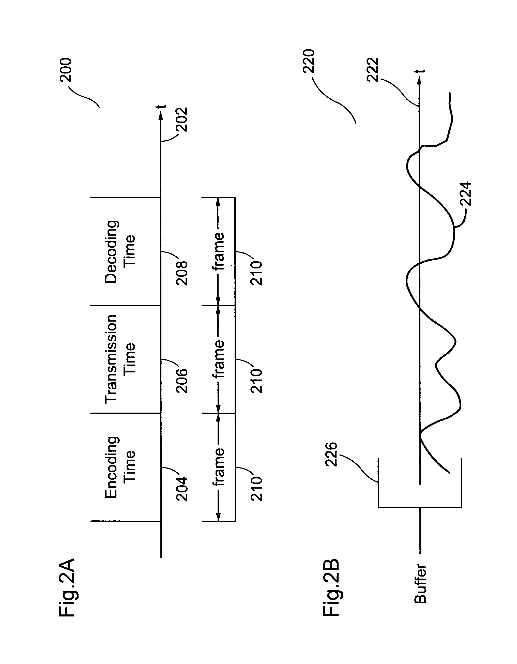
[0006]Embodiments of the present invention control the video encoder output bit stream rate for scenarios requiring transmission latencies lower than the duration of a single frame in a network. The embodiments of the present invention do not implement large buffers to handle the bit rate increase due to complex video data encoding, but, instead, performs a process that allows encoding to occur with a low latency. A frame or less may be buffered according to the disclosed embodiments. The proposed rate control also may work with higher latencies to also cover systems that do not require low latency.
[0007]The disclosed embodiments allocate the necessary bits within a frame to achieve a specific maximum bit rate. By staying below the network capacity, the video transmission / reception system results a low latency desired for real-time video playback.
[0008]The disclosed embodiments control the bit allocation at a sub-frame level. A frame is divided into smaller blocks, known as rate control blocks. Rate control blocks are used as the basic unit for bit allocation. This bit allocation achieves the target bit rate desired by the system as well as meet latency constraints. The disclosed embodiments may use the slice partitioning capabilities of the video encoder. This feature allows the decoder to decode the rate control blocks independently. Whenever the encoded data size for each rate control block is lower than the bit rate allocated by the rate control, the end-to-end latency for each rate control block will be as much as the specified maximum latency.

Problems solved by technology

Nevertheless, a probability exists of producing an erroneous estimation that may lead to an instance where the allocated bits for the rate control block are not achieved.
In other words, the bit rate may be higher than the target bit rate and exceed buffer capacity, thereby putting latency requirements at risk.

Method used


Image

  • Low latency rate control system and method
  • Low latency rate control system and method
  • Low latency rate control system and method

Examples


Embodiment Construction

[0020]Aspects of the invention are disclosed in the accompanying description. Alternate embodiments of the present invention and their equivalents are devised without parting from the spirit or scope of the present invention. It should be noted that like elements disclosed below are indicated by like reference numbers in the drawings.

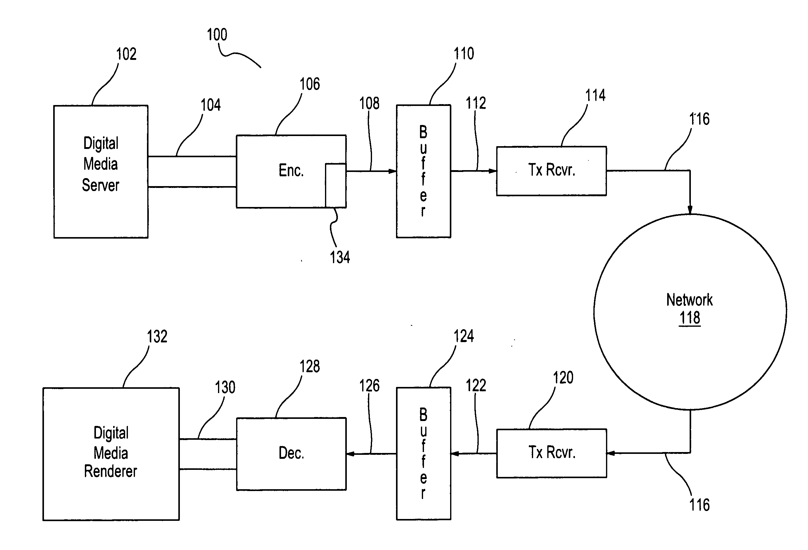
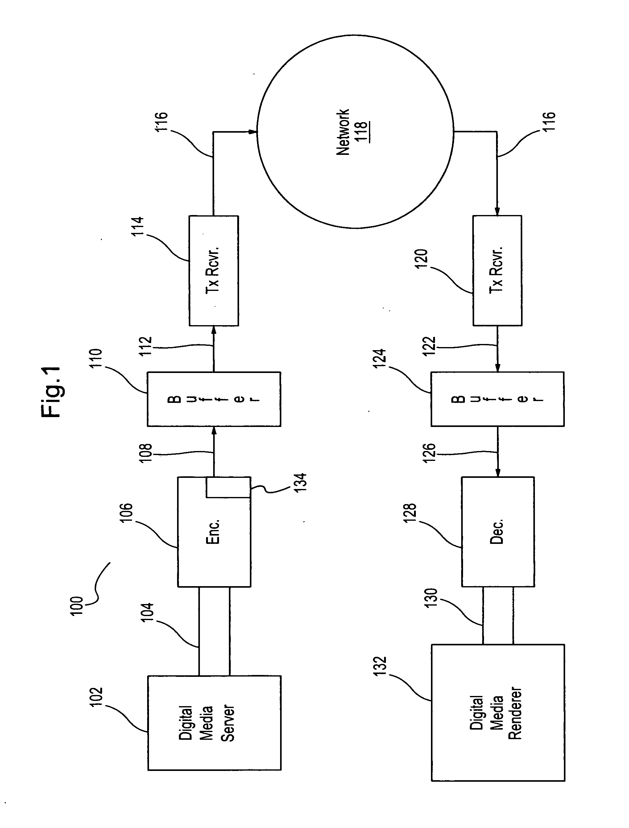
[0021]FIG. 1 depicts a system 100 for transmitting and receiving video signal data according to the disclosed embodiments. System 100 may be any system or collection of devices that connect over a network to share information. Image frames within a video signal is received to be sent over the network. The data within the image frame is encoded for transmission using various encoding techniques.

[0022]System 100, for example, may be a gaming system where video content is generated in the gaming console and then transmitted to a high-definition digital media renderer, such as a flat-screen television. Alternatively, system 100 may be a security monitoring ...


PUM


Abstract

An encoder within a video transmission system controls the bit allocation at a sub-frame level. A frame is divided into smaller blocks, known as rate control blocks. Rate control blocks are used as the basic unit for bit allocation. This bit allocation achieves the target bit rate desired by the system as well as meet latency constraints. The encoder uses the slice partitioning capabilities to generate the rate control blocks using one or more slices of the image frame. This feature allows the decoder to decode the rate control blocks independently and ensures that the encoded data size for each rate control block is allocated. The encoder also detects the overflow condition for the buffer and performing an operation to avoid the overflow condition based on whether the image frame is an inter-frame or a intra-frame.

Description

FIELD OF THE INVENTION[0001]The present invention relates to transferring video signals over a network. More particularly, the present invention relates to sending and receiving complex video signals over a network having low latency constraints.DISCUSSION OF THE RELATED ART[0002]In known video transmission / reception systems, data content from a digital media server is encoded and sent to be decoded for playback on a digital media renderer. Video content, however, can be quite complex as it changes over time. As complexity changes, so does the bit rate needed for quality transmission of the content. For a given compression quality level, complexity of the video data results in a higher bit rate for encoding the data. The capacity of the network, however, may remain constant over time and does not change due to the complexity of the video data or increased bit rate.[0003]To accommodate this bit rate fluctuation at the video encoder, rate control is used to create a constant bit rate ...

Claims


Application Information

Patent Timeline
IPC IPC(8): H04N7/26
CPCH04N19/176H04N19/147H04N19/172H04N19/174H04N19/61H04N19/115H04N19/152H04N19/103H04N21/2662H04N21/238
Inventor DUENAS, ALBERTORONCERO IZQUIERDO, FRANCISCO J.GARCIA, GORKA
Owner MARVELL ASIA PTE LTD
Learn More