Method and apparatus for detecting a parity error in a sequence of dqpsk symbols of a digital transmission system

a digital transmission system and parity error technology, applied in the field of error detection in dqpsk (differential quadrature phase shift keying) communication systems, can solve the problems of differential decoding, increased power consumption, and increased noise in transmission, so as to reduce the complexity of dsp and reduce power consumption, the effect of less gate coun

Active Publication Date: 2012-11-15
HUAWEI TECH CO LTD
View PDF2 Cites 12 Cited by
  • Summary
  • Abstract
  • Description
  • Claims
  • Application Information

AI Technical Summary

Benefits of technology

[0005]One of the objects of the present disclosure is to provide an efficient concept for mitigating the differential decoding penalty exhibiting high performance and low complexity.
[0013]Using DQPSK avoids the need for possibly complex carrier-recovery schemes to provide an accurate phase estimate and is used as an attractive alternative to ordinary PSK. A constant or slowly time-varying carrier phase offset is cancelled by this method and carrier frequency offset translates into a constant phase offset such that low carrier frequency offsets can be tolerated with only minor penalty. Therefore, a carrier frequency synchronization before SD decoding may be performed but is not necessary.
[0015]Typically, several stages of digital equalization and synchronization are applied to the received signal such as chromatic dispersion compensation, timing recovery and adaptive filters to mitigate polarization effects, e.g. finite impulse response filters (FIR) to perform time-domain equalization (TDEQ). After equalization, typically one discrete, complex valued signal per polarization can be obtained, which is referred to x(n) and y(n) respectively.
[0024]According to the first aspect, phase differences between DQPSK symbols are easy to calculate such that the method provides a low complexity. By using super-parity symbols the method provides a mechanism to detect errors in parity symbols which may be corrected before detection of errors in the sequence of DQPSK symbols is initiated. Thus, the method provides an efficient mechanism for mitigating the differential decoding penalty while exhibiting high performance and low complexity.
[0053]For a low-cost, coherent detection receiver, e.g. a coherent single-polarization (SP) 40G DQPSK receiver, according to an implementation form of the second aspect, SD (soft differential) decoding allows to remove the carrier recovery. This reduces the complexity of the DSP tremendously by less gate count, less power consumption and less latency. The combination of SD decoding with the improved NEC and no carrier recovery, according to implementation forms of the second aspect, results in a low cost system. The calculated parities detect certain error patterns and mark them as erroneous. Some of those error patterns but not necessarily all are corrected by the non-redundant error correction according to implementation forms of the second aspect. According to some implementation forms of the second aspect, the information is provided to subsequent forward error correction units (FEC) as additional soft information to pre-determine erroneous error patterns. Thus, non-redundant error correction (NEC) improves forward error correction (FEC). Apparatuses, according to implementation forms of the second aspect, are compatible with any existing DSP structure. They provide improved mitigation of the SD penalty with low complexity.

Problems solved by technology

For digital transmission systems, in particular optical transmission systems, transmission is sensitive to noise.
Differential decoding, however, introduces a Bit Error Rate (BER) penalty in the B2B (Back-to-Back) transmission between a transmitting device and a receiving device.
Thus, the total noise power is doubled, which translates into an (optical) signal-to-noise ratio degradation.
These methods, however, suffer from complex implementation.
Non-redundant error correction, however, may deliver poor performance.

Method used


Image

  • Method and apparatus for detecting a parity error in a sequence of dqpsk symbols of a digital transmission system
  • Method and apparatus for detecting a parity error in a sequence of dqpsk symbols of a digital transmission system
  • Method and apparatus for detecting a parity error in a sequence of dqpsk symbols of a digital transmission system

Examples


Embodiment Construction

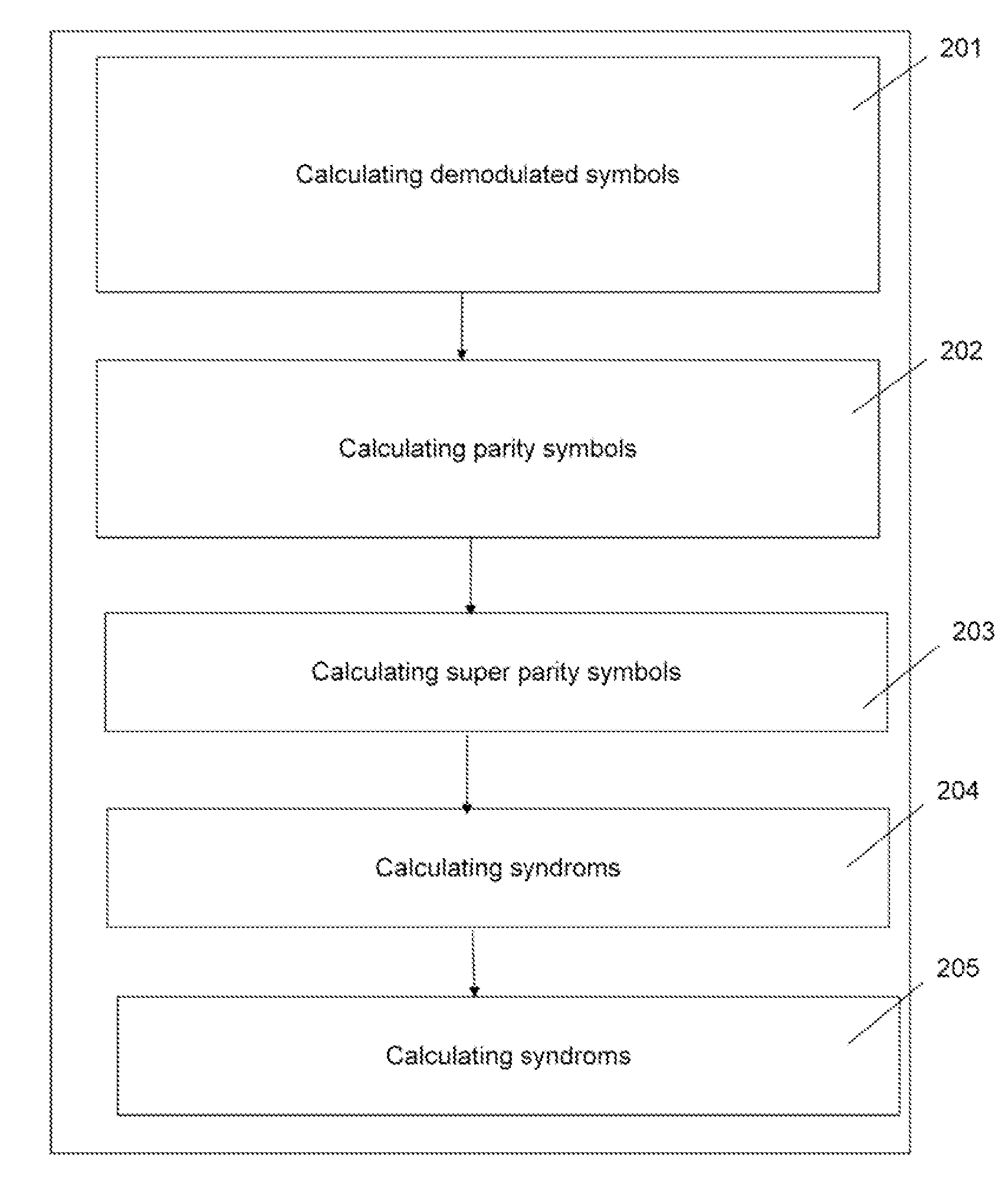
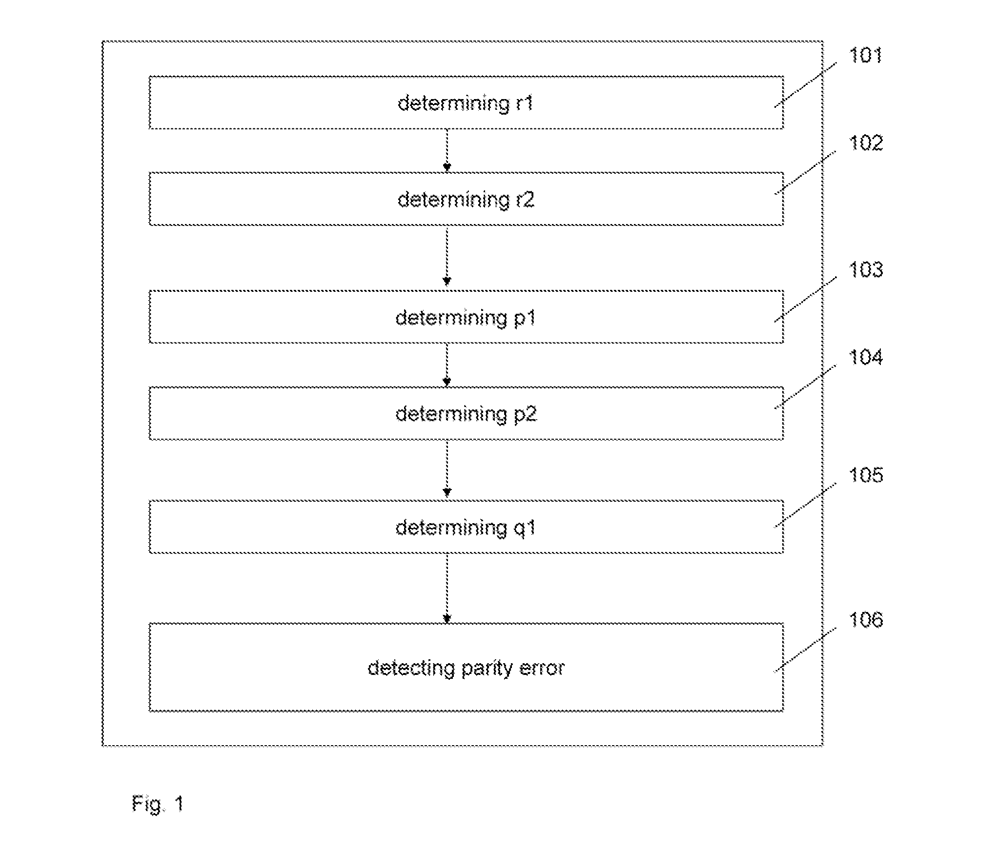
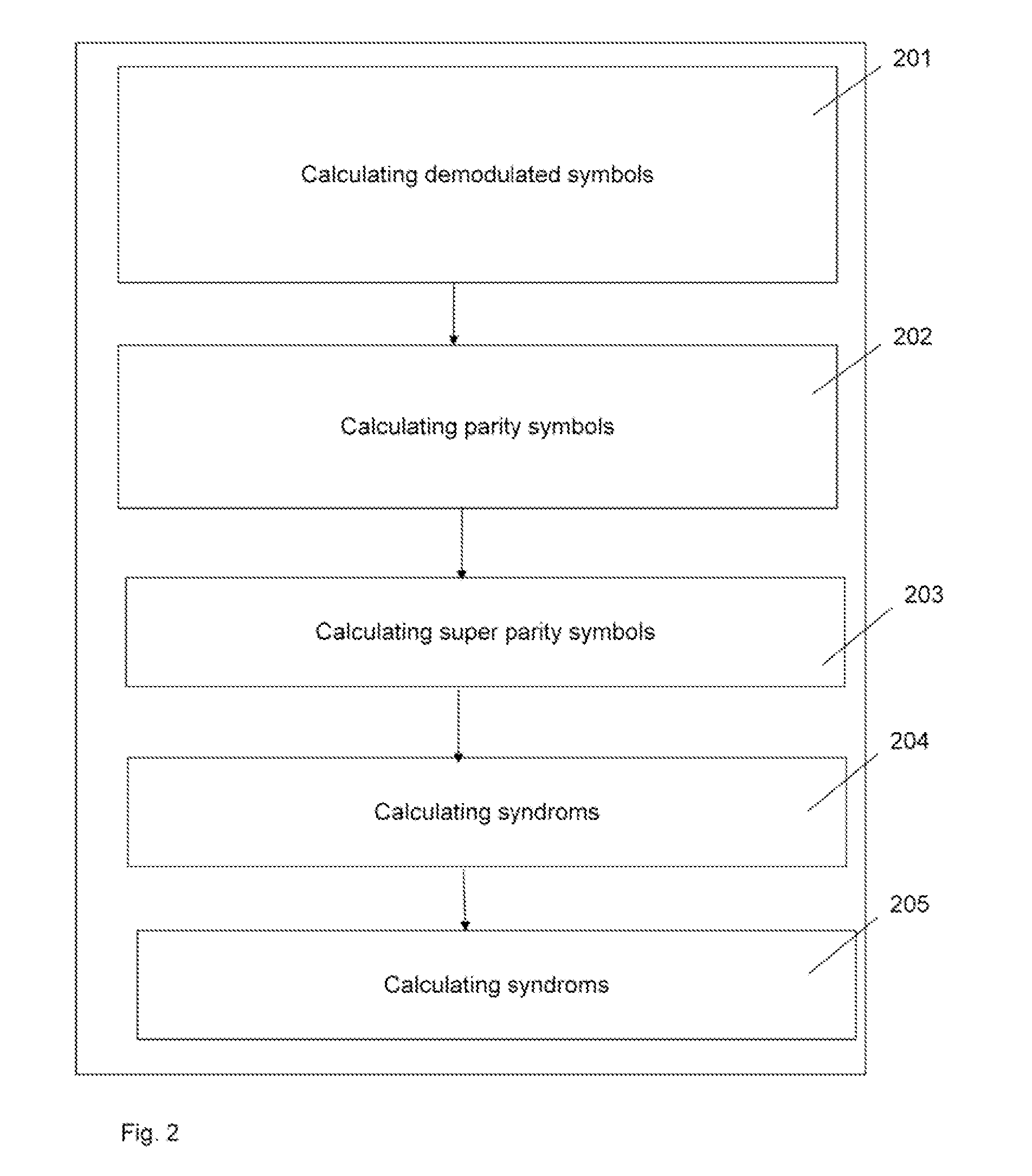
[0062]FIG. 1 shows a block diagram of a method for detecting a parity error in a sequence of DQPSK symbols according to an implementation form. The method comprises a first step 101“determining r1 as parity between x(n−2) and x(n−1)” and a second step 102“determining r2 as parity between x(n−1) and x(n)”, wherein x(n−2), x(n−1), x(n) are contiguous symbols of a sequence of DQPSK symbols. According to this implementation form, step 101 is performed before step 102. According to an other implementation form, step 102 is performed before step 101. The method comprises a third step 103“determining p1 as parity between x(n−k) and x(n)” and a fourth step 104“determining p2 as parity between x(n−k−m) and x(n−k)”, wherein x(n), x(n−k), x(n−k−m) are non-contiguous symbols of the sequence of DQPSK symbols. According to this implementation form, step 103 is performed before step 104. According to another implementation form, step 104 is performed before step 103. According to this implementati...


PUM


Abstract

The present disclosure relates to a method for detecting a parity error in a sequence of DQPSK symbols of a digital transmission system, comprising determining a first demodulated symbol r1; determining a second demodulated symbol r2; determining a first parity symbol p1; determining a second parity symbol p2; determining a super-parity symbol q1; and detecting a parity error in the sequence of DQPSK symbols by comparing a combination of the first parity symbol p1 and the second parity symbol p2 against the super-parity symbol q1, wherein a parity between two DQPSK symbols describes a phase difference between the two DQPSK symbols.

Description

CROSS-REFERENCE TO RELATED APPLICATION[0001]This application is a continuation of International Application No. PCT / CN2011 / 073878, filed on May 10, 2011, entitled “Method And Apparatus For Detecting A Parity Error In A Sequence Of DQPSK Symbols Of A Digital Transmission System”, which is hereby incorporated herein by reference.FIELD OF THE INVENTION[0002]The present disclosure relates to error detection in DQPSK (Differential Quadrature Phase Shift Keying) communication systems.BACKGROUND OF THE INVENTION[0003]For digital transmission systems, in particular optical transmission systems, transmission is sensitive to noise. Differential decoding is used to reduce error bursts induced by phase slips. Soft differential (SD) decoding proves excellent tolerance against non-linear phase noise. Differential decoding, however, introduces a Bit Error Rate (BER) penalty in the B2B (Back-to-Back) transmission between a transmitting device and a receiving device. In the case of soft differential...

Claims


Application Information

Patent Timeline
Patent Type & Authority Applications(United States)
IPC IPC(8): H03M13/09H03M13/05G06F11/10
CPCH03M13/3746H03M13/6325H04L27/2331H04L1/0063H04L1/0045
Inventor HAUSKE, FABIAN NIKOLAUSBAUCH, GERHARDPFLUEGER, DORIS
Owner HUAWEI TECH CO LTD
Why Eureka
Try Eureka