

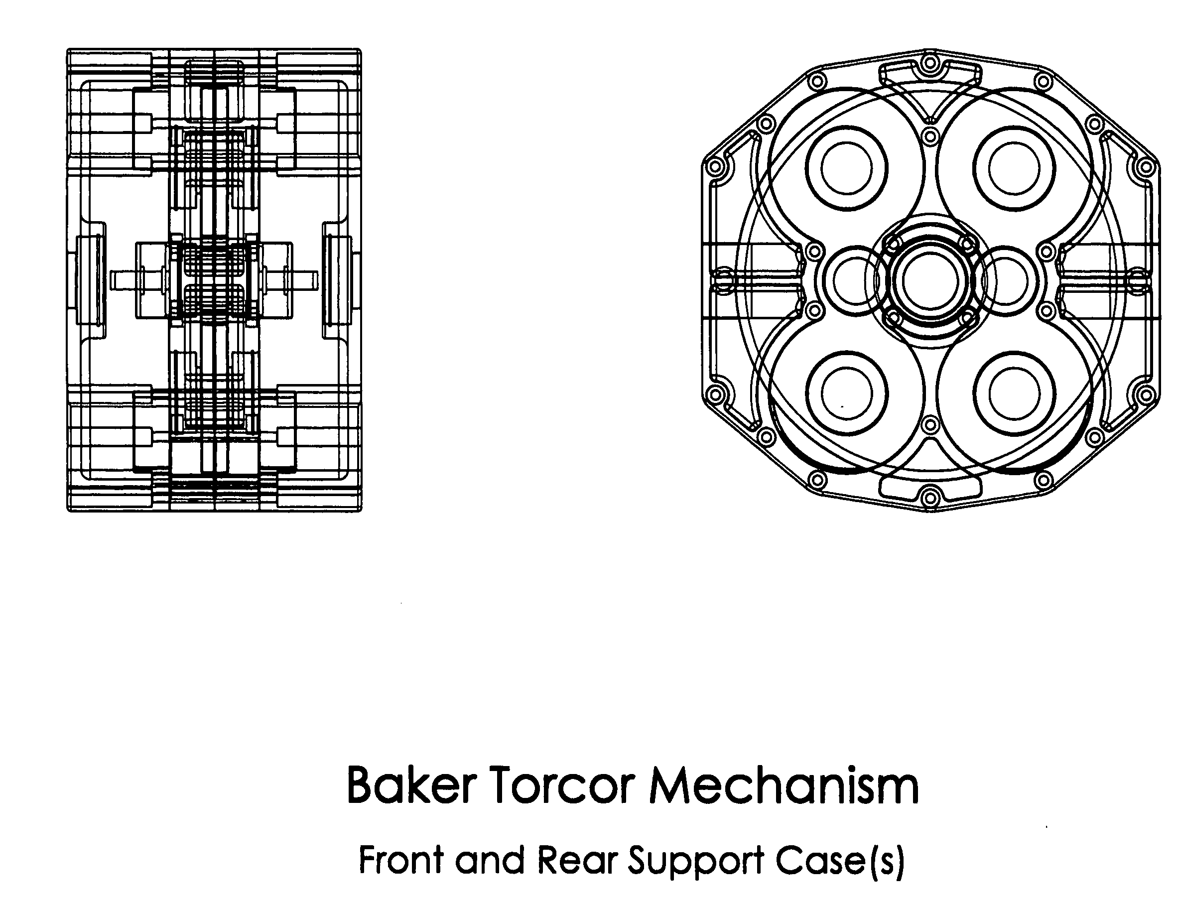
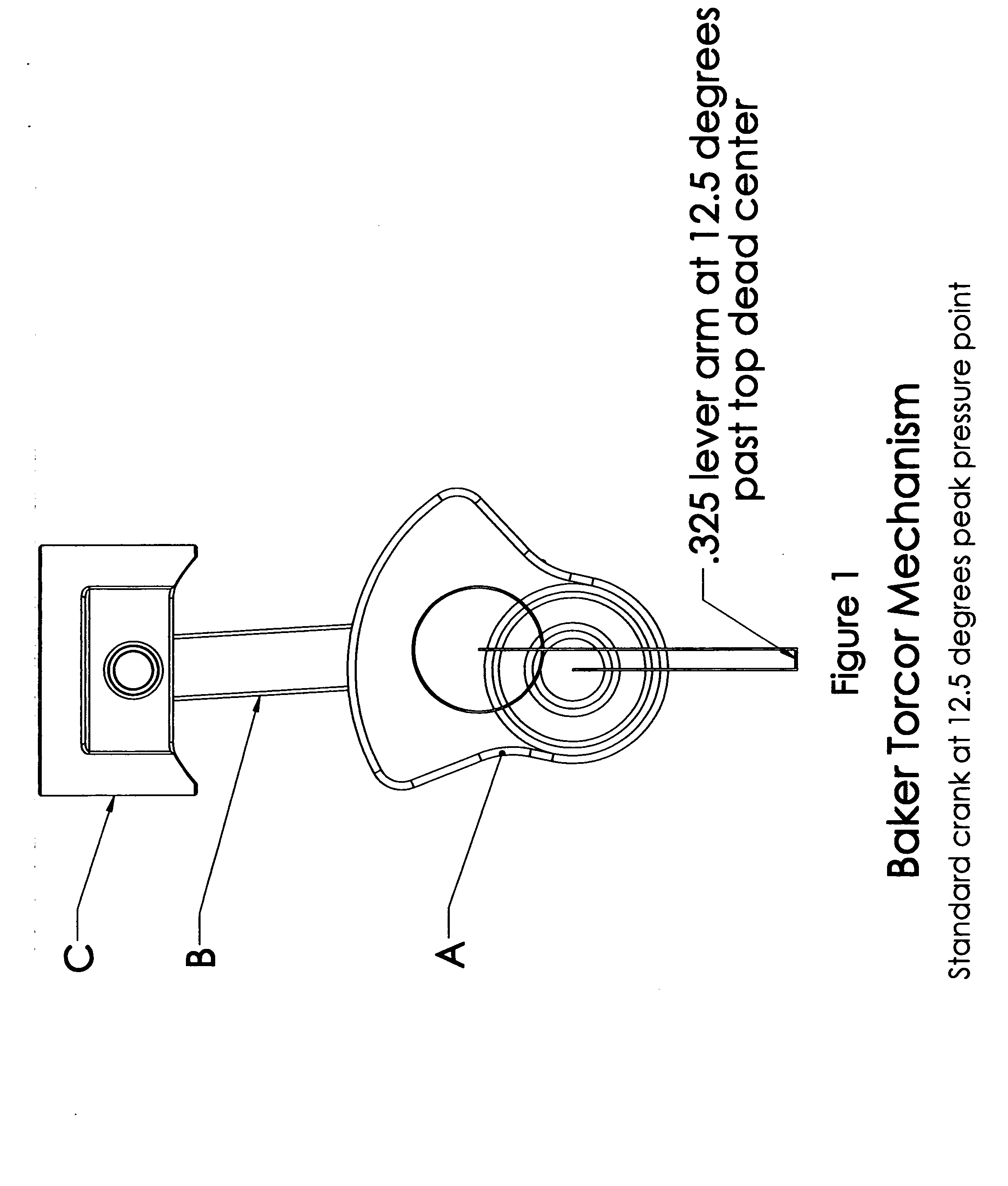
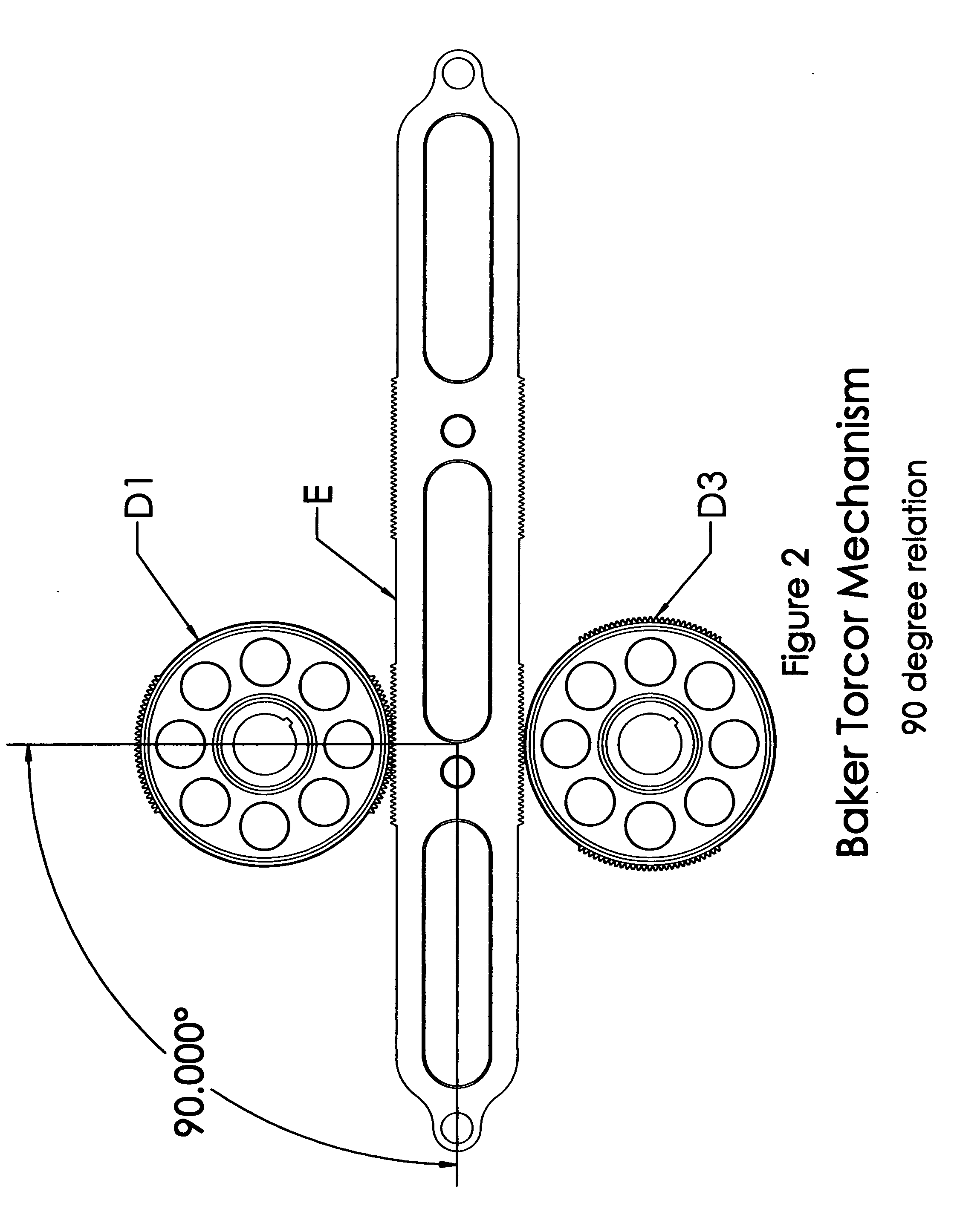
Baker Torcor motion conversion mechanism
a technology of motion conversion mechanism and torcor, which is applied in the direction of mechanical equipment, machines/engines, etc., can solve the problems of reducing the efficiency of mechanical motion conversion efficiency, reducing the efficiency of mechanical motion conversion, and low-efficiency crankshafts, etc., to achieve energy-saving, energy-saving, and reduce energy consumption
- Summary
- Abstract
- Description
- Claims
- Application Information
AI Technical Summary
Benefits of technology
Problems solved by technology
Method used
Image

Examples
second embodiment
[0113]In a second embodiment of the present invention, operating as described but without the fuel delivery and ignition system components required for an ICE application, would prove to be of superior design and efficiency when applied to pneumatic systems. By utilizing the mechanism described herein, the conversion of a rotary motion to a linear motion is optimized and the linear pumping device achieves and maintains the mathematically optimum ninety degree angle throughout the linear components travel.
[0114]As rotary input motion drives the center gear, center mesh gears, intermediate gears and then the interrupted front gears, the linear motion of the rack and attached pumping pistons, devices or apparatus achieves increased efficiency over traditional crankshaft based air compressors. The inverse operation provides the means for similar functionality and operational efficiency when applied to air driven motors.
third embodiment
[0115]In a third embodiment, the present invention, operating as described but without the fuel delivery and ignition system components required for an ICE application, would prove to be of superior design and efficiency when applied to piston hydraulic machines, such as pumping devices.
[0116]As rotary input motion drives the center gear, center mesh gears, intermediate gears and then the interrupted front gears, the linear motion of the rack and attached hydraulic pumping pistons, devices or apparatus achieves increased efficiency over traditional crankshaft based hydraulic pumps by the mechanical functionality as described in the description of operation herein. The inverse operation provides the means for similar functionality and operational efficiency when applied to hydraulic motors.
forth embodiment
[0117]In a fourth embodiment, the present invention, operating as described but without the fuel delivery and ignition system components required for an ICE application, would prove to be of superior design and efficiency when applied to rotary and / or linear induction of magnetic fields and the means to provide electrical energy production.
[0118]As rotary input motion drives the center gear, center mesh gears, intermediate gears and then the interrupted front gears, the linear motion of the rack and attached magnetic and / or electromagnetic device or apparatus move within a device or apparatus that provides the counterforce of magnetic and / or electromagnetic fields that allow for linear electrical generation. The exact opposite is true for electric motor operation.
PUM
 Abstract
Description
Claims
Application Information