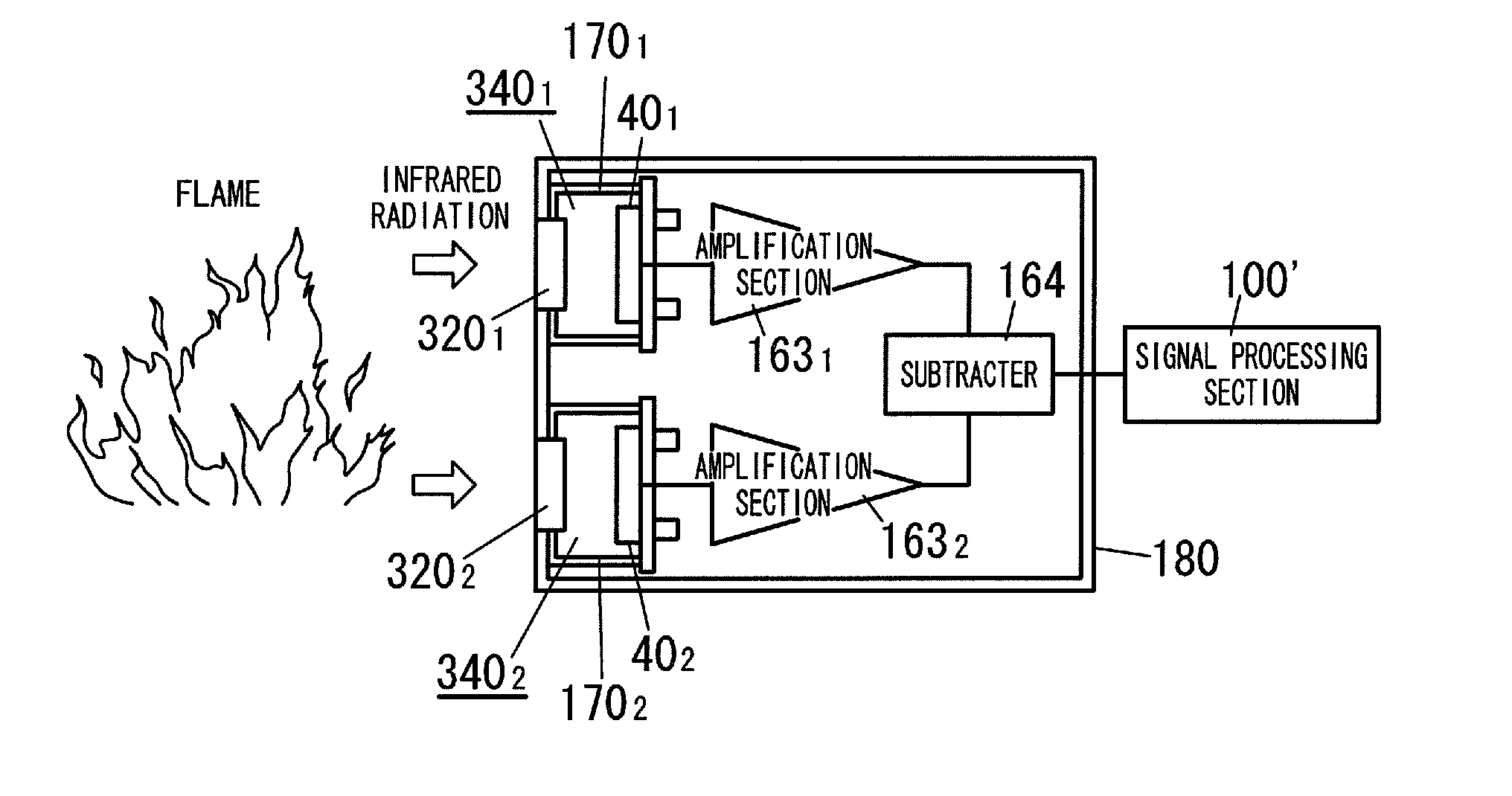
[0014]Incidentally, it can be considered that the infrared
gas detector having the structure shown in FIGS. 28A and 28B disclosed in
Patent Document 3 described above is used as the infrared
flame detector. However, in its production, it is necessary to form a plurality of types of the infrared optical filters 201, 202, 203, and 204 having different filter characteristics in mutually different wafers, dice the infrared optical filters 201, 202, 203, and 204 from the individual wafers, and then bond the infrared optical filters 201, 202, 203, and 204 having different filter characteristics to one another by using the
adhesive 19. As a result, in such infrared
flame detector, the cost thereof is high, it is difficult to reduce the size of the infrared optical element module constituted by a plurality of the infrared optical elements 401, 402, 403, and 404, and the distance between the centers of the infrared radiation receiving elements 401, 402, 403, and 404 is increased so that a difference in
optical path length among the infrared radiations reaching the infrared radiation receiving elements 401, 402, 403, and 404 is increased. That is, in such infrared
flame detector, a difference in
optical path length between detected light having infrared radiation of 4.3 μm as a first selective wavelength and reference light having infrared radiation of a second selective wavelength other than the first selective wavelength is disadvantageously increased. In addition, in such infrared flame detector, the light receiving efficiency of each of the infrared radiation receiving elements 401, 402, 403, and 404 is lowered.
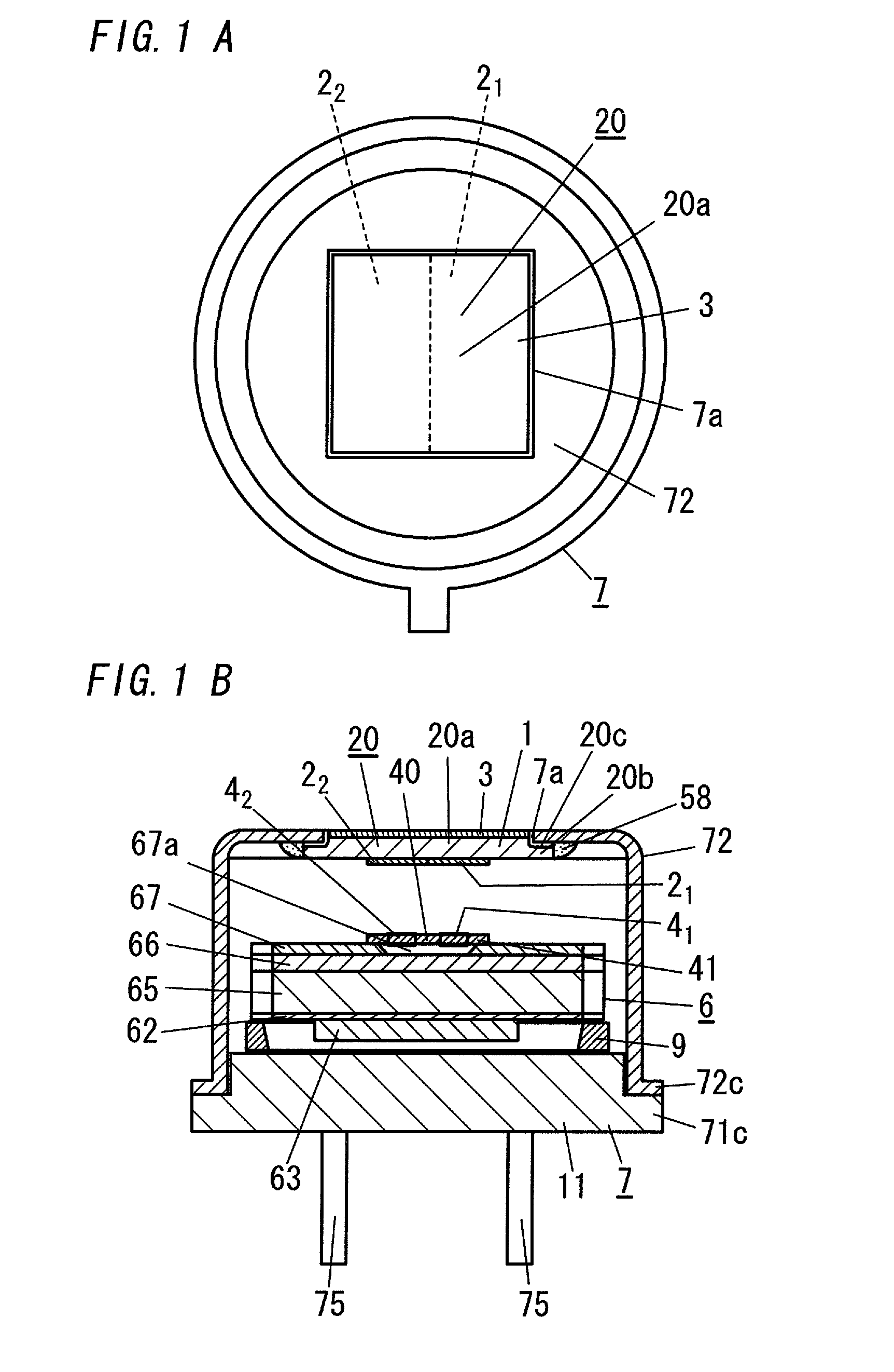
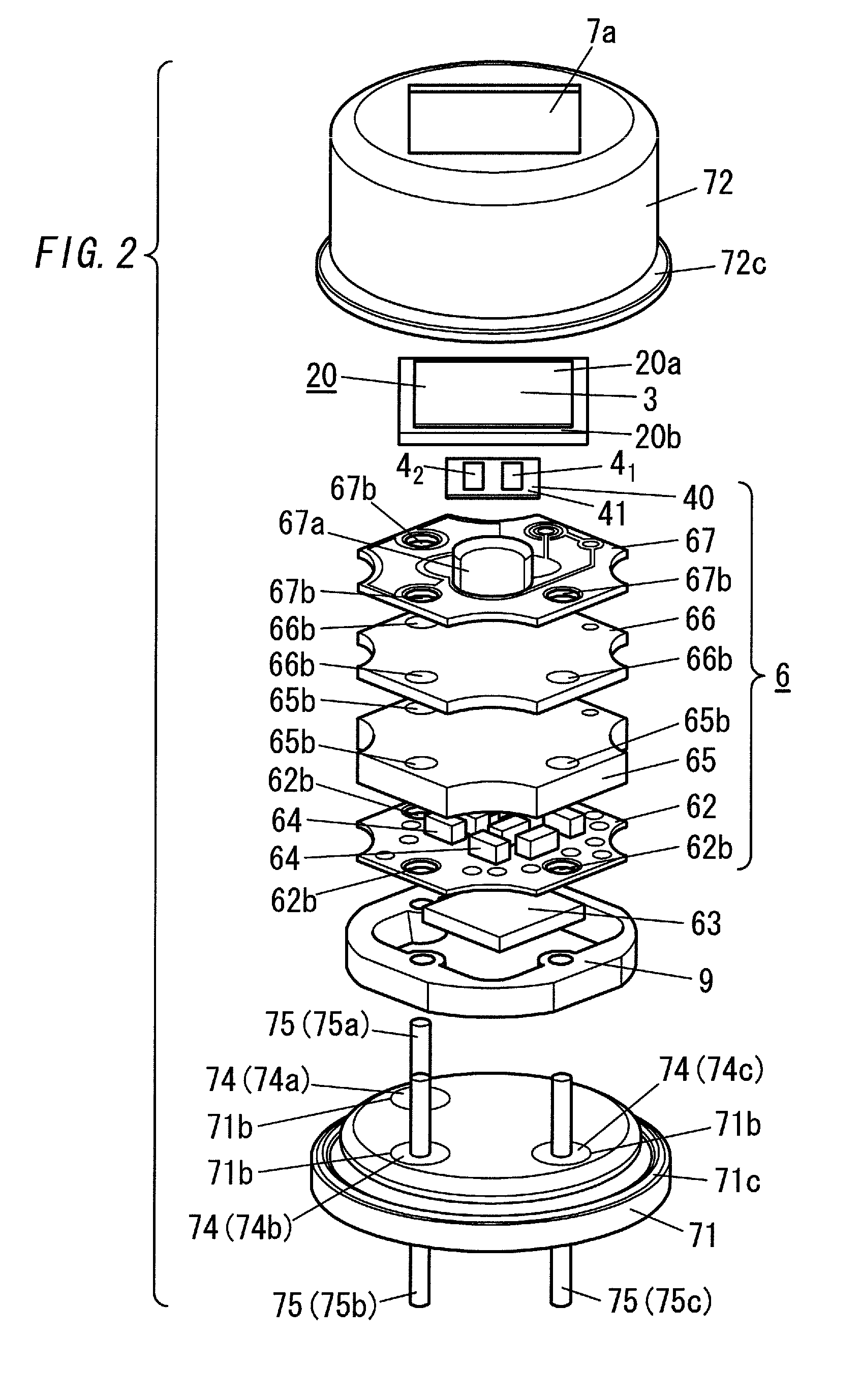
[0015]Additionally, in the infrared
gas detector having the structure shown in FIGS. 28A and 28B, since the
light transmission window 7a provided in the front wall of the cap 72 is closed by the infrared radiation transmitting member 80 constituted by the
sapphire substrate, far-infrared radiation of ambient light such as
sunlight or illumination light that causes noises can be blocked by the infrared radiation transmitting member 80. However, the number of steps required for the
assembly is increased with an increase in the number of components and, in addition, the
sapphire substrate is expensive and difficult to
processing such as dicing so that the cost is increased. Further, when the number of
layers of the multilayer film in each of the infrared optical filters 201, 202, 203, and 204 is increased, although the far-infrared radiation can be blocked while the
narrowband band-pass filter is realized, the cost is increased.
[0016]Furthermore, in the infrared
gas detector having the structure shown in FIGS. 28A and 28B, when a conductive
adhesive such as a
silver paste or the like is used as the
adhesive 19 for conduction of
electricity among the infrared optical filters 201, 202, 203, and 204, the
mechanical strength thereof is lowered. Moreover, as in the infrared flame detector having the structure shown in FIGS. 25A and 25B, in the case of the infrared flame detector in which the infrared
optical filter 20′ is formed by selectively depositing the
dielectric multilayer film designed according to transmission characteristics of each of the band-pass filter sections 2021, 2022, 2023, and 2024 four times on the single glass substrate, since it is necessary to sequentially form the multilayer films constituting the individual band-pass filter sections 2021, 2022, 2023, and 2024, there is a problem that the production cost is increased. In addition, in the case of the infrared flame detector in which the infrared
optical filter 20′ is formed by bonding the four fan-shaped band-pass filter sections 2021, 2022, 2023, and 2024 to one another, it is necessary to separately form the band-pass filter sections 2021, 2022, 2023, and 2024 having different transmission characteristics and form them into the fan shape so that there is a problem that the production cost is increased and the
mechanical strength is lowered.
[0018]In contrast to this, in the infrared
optical module having the structure shown in FIG. 27 disclosed in
Patent Document 2 described above, the two infrared radiation receiving elements 4001 and 4002 are formed on one surface side of the substrate 300 constituted by the MgO substrate, and the
narrowband transmission filter sections 2001 and 2002 having mutually different transmission wavelengths are stacked on the infrared radiation receiving elements 4001 and 4002. Consequently, in the infrared
optical module, it is possible to reduce the distance between the centers of the narrowband transmission filter sections 2001 and 2002, reduce the difference in
optical path length between the infrared radiation of the first selective wavelength (4.3 μm) and the infrared radiation (reference light) of the second selective wavelength other than the first selective wavelength, and achieve a reduction in cost.
[0019]However, in the infrared
optical module having the structure shown in FIG. 27, although each of the infrared radiation receiving elements 4001 and 4002 is a
thermal infrared radiation receiving element such as the pyroelectric element or the like, the narrowband transmission filter sections 2001 and 2002 are stacked directly on the infrared radiation receiving elements 4001 and 4002. As a result, in the infrared optical module, the thermal capacity is increased and it becomes difficult to secure
thermal insulation properties so that response and sensitivity are lowered.

