
Apparatus and Method for Area Disinfection Using Ultraviolet Light

a technology of ultraviolet light and apparatus, applied in the field of apparatus and method for disinfecting surfaces, can solve the problems of increasing health care costs, severe, if not lethal, affect on patients, etc., and achieves the effects of minimizing shadows, thorough disinfection, and convenient positioning of the ula

Inactive Publication Date: 2012-12-06
GH GLOBAL ENTERPRISES
View PDF6 Cites 118 Cited by
  • Summary
  • Abstract
  • Description
  • Claims
  • Application Information

AI Technical Summary

Benefits of technology

[0014]The present invention is also directed to a surface disinfection system comprising a plurality of independently placeable and independently controllable portable ULAs, and a control station for remotely controlling activation and deactivation of the plurality of light assemblies by wireless data communication. Each ULA includes a tubular lamp, for example, an amalgam lamp, vertically oriented and positioned within a protective quartz sleeve, wherein the lamp is capable of UV-C emission at a wavelength of about 254 nm. The lamp is mounted on a portable base unit, preferably with lockable castors for easy positioning of the ULA. Within the base unit are electronic components for generating power to the lamp, for detecting motion within the room being sterilized, for detecting fluence levels, for generating an audible alarm, and for wireless communication with a control station which is located remotely outside the room during operation of the system. Each base unit preferably may be connected directly for power to a 110v AC room receptacle. The plurality of ULAs permits strategic placement of the light emitting sources to minimize shadows and thereby provides a more thorough degree of disinfection than is possible with a single-location device as in the prior art. Further, independent control of the plurality of ULAs permits shutting down one such unit operating in an area requiring less lengthy irradiation, such as a small bathroom. This minimizes the total exposure to which UV-degradable materials may be subject by repeated disinfections over time. In one embodiment, a portable cart housing the control station includes a dock for storing and transporting the plurality of base units between uses.
[0015]In operation, the ULAs are unloaded from the cart and positioned strategically within the area to be irradiated, taking into account various factors including room width and length and the minimization of shadows when the ULAs are energized. The ULAs are plugged in, and the cart is rolled outside the area. The area is checked for absence of all personnel and then temporarily sealed against re-entry. The control station is programmed for operation of the ULAs and the ULAs are energized. At the conclusion of the programmed time period, the ULAs are denergized and the area is opened for re-entry of personnel. The ULAs are unplugged and reloaded onto the cart for future use.

Problems solved by technology

The problem has become so serious that many hospitals must close critical areas, such as operation theaters and intensive care units, to eradicate pathogens via terminal cleaning.
HAIs contribute to rising health care costs and can lead to severe, if not lethal, affects on patients.
The short wavelength of UV-C is harmful to forms of life at the micro-organic level by destroying nucleic acids in these organisms so that their DNA and / or RNA chemical structure is disrupted by the UV radiation.
The 185 nm emission causes disassociation of oxygen molecules to create ozone, a gas with a short half life that is an air pollutant with harmful effects on respiratory systems.
Therefore, UV lamps that generate ozone are generally undesirable for use in closed areas.
Environments with obstacles that block the source are not as effective, and UV reflectance may be low and unreliable.
Further, auxiliary spaces, such a bathroom that commonly accompanies a hospital room, cannot be properly irradiated by a single UVAS, so a second UVAS is required.

Method used


Image

  • Apparatus and Method for Area Disinfection Using Ultraviolet Light
  • Apparatus and Method for Area Disinfection Using Ultraviolet Light
  • Apparatus and Method for Area Disinfection Using Ultraviolet Light

Examples


Embodiment Construction

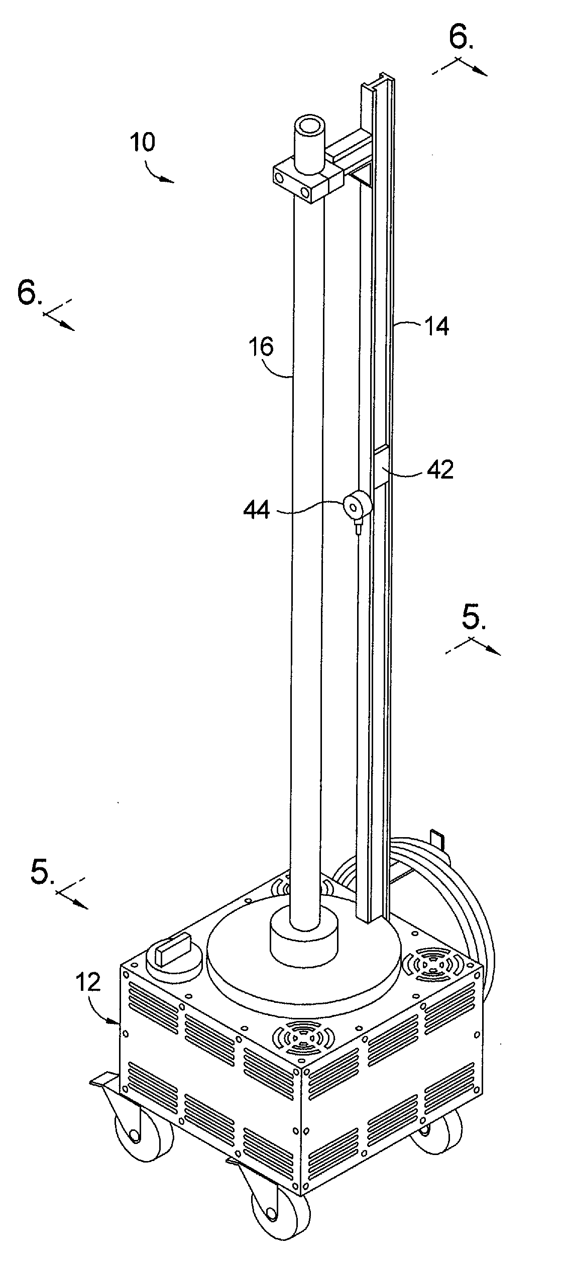
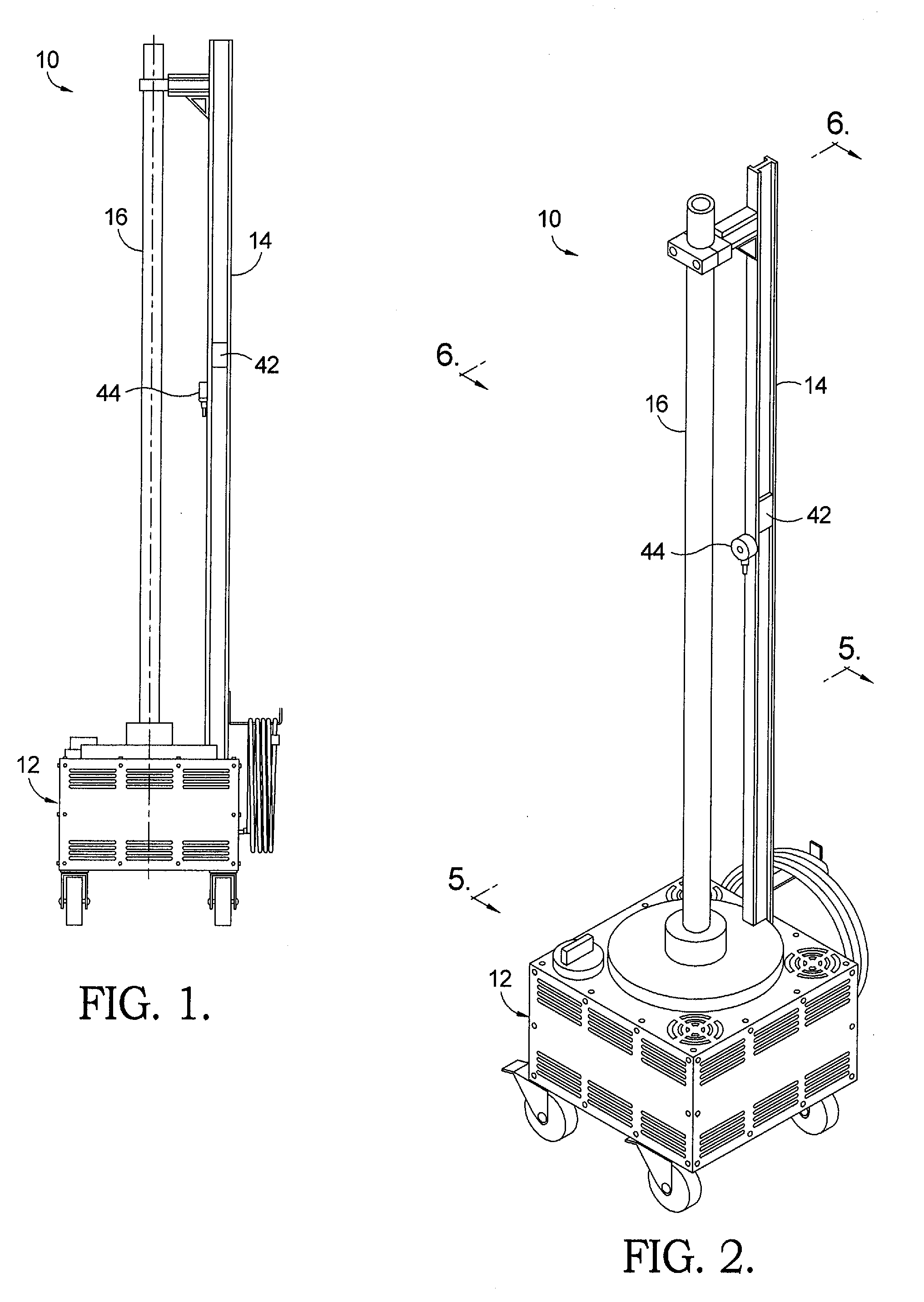
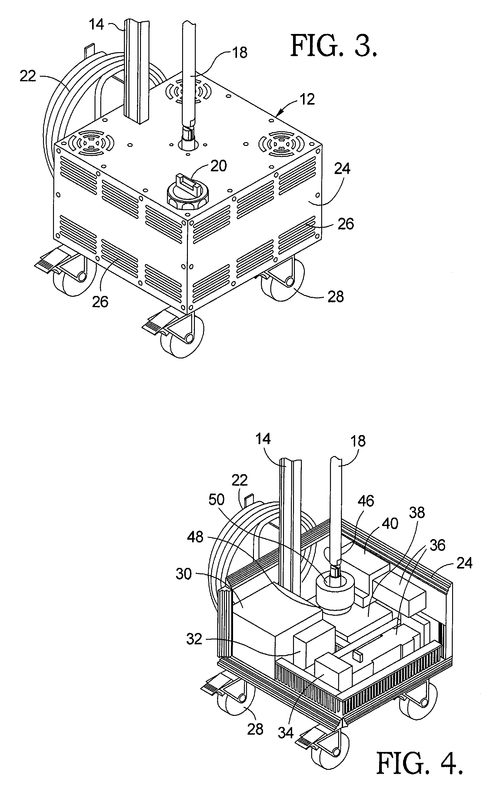
[0033]Referring to the drawings in more detail, and initially to FIGS. 1 through 6, one embodiment 10 of an ultraviolet light emitting assembly (ULA) in accordance with the present invention generally comprises a base unit 12, a vertical support rail 14 mounted to base unit 12, a transparent protective sleeve 16 supported by support rail 14, and a UV-C light emitting source 18 positioned within sleeve 16. In accordance with one aspect of the present invention, a plurality of ULAs may be associated with a control station 19 (FIG. 7) to form a system for disinfecting an area, such as a room in a hospital or clinic. In operation of the system, the plurality of ULAs are strategically placed within a room to be disinfected so that, when control station 19 operates to remotely activate and deactivate the plurality of ULAs to emit UV-C light within the room, the shadows within the room are minimized and the surfaces within the room are efficiently disinfected.

[0034]As best seen in FIGS. 3 ...


PUM


Abstract

A surface disinfection system comprising a plurality of independently placeable and controllable portable ultraviolet light emitting assemblies (ULAs), and a control station for remotely controlling the plurality of light assemblies. A cart housing the control station includes a dock for storing and transporting the assemblies. Each assembly includes a tubular UV-C lamp mounted on a portable base unit that includes electronic components for generating power to the lamp, detecting motion within the room being sterilized, detecting fluence levels and for audible alarm, and for wireless communication with the control station which is located outside the room during operation of the system. Using a plurality of ULAs permits strategic placement of the radiation sources to minimize shadows and thereby provides a thorough degree of disinfection. Independent control of the ULAs permits shutting down any unit to minimize the exposure to which UV-degradable materials are subject by repeated disinfections over time.

Description

TECHNICAL FIELD[0001]The present invention relates to an apparatus and method for disinfecting surfaces; more particularly, to an apparatus and method for disinfecting surfaces using ultraviolet light; and most particularly, to an improved apparatus and method for the disinfection of rooms in, for example, hospitals and clinics, using UV-C light.BACKGROUND OF THE INVENTION[0002]Surface disinfection of patient care areas is a key factor in the constant battle to reduce or eliminate Hospital Acquired Infections (HAIs), also known in the art as nosocomial diseases or infections. Increased evidence published in scientific literature confirms that Clostridium difficile, MRSA, VRE, Acinetobacter baumannii, Bacillus subtilis var. niger, Bacillus anthracis Sterne, and influenza are transmitted via environmental surfaces and air. The problem has become so serious that many hospitals must close critical areas, such as operation theaters and intensive care units, to eradicate pathogens via ter...

Claims


Application Information

Patent Timeline
IPC IPC(8): B01J19/12G01J1/42
CPCA61L2/10
Inventor HENSON, BRIAN ROY
Owner GH GLOBAL ENTERPRISES
Learn More