METHOD AND SYSTEM FOR LOW-NOx DUAL-FUEL COMBUSTION OF LIQUID AND/OR GASEOUS FUELS

Active Publication Date: 2012-12-13
GAS TECH INST
View PDF21 Cites 35 Cited by
  • Summary
  • Abstract
  • Description
  • Claims
  • Application Information

AI Technical Summary

Benefits of technology

[0011]It is, thus, one object of this invention to provide a method and apparatus for combustion of a liquid fuel or a mixture of liquid fuel and gaseous fuel which is able to meet the objectives of maintaining high efficiency and low emissions to meet the limits set by the U.S. Environmental Protection Agency (EPA) in different regions of the United States, including California.
[0012]This and other objects of this invention are addressed by a method and apparatus for combustion in which a pressurized preheated liquid fuel is atomized, producing an atomized liquid fuel and at least a portion of the atomized liquid fuel is flash vaporized, producing a liquid-fuel mixture comprising the atomized liquid fuel and the vaporized fuel. The mixture of atomized liquid fuel and vaporized fuel, referred to herein as a liquid-fuel mixture, is mixed with a primary combustion oxidant in a mixing chamber, producing a mixture of fuel and oxidant, referred to herein as a fuel/oxidant mixture, having a primary stoichiometry less than about 1.0, i.e. a fuel-rich stoichiometry. The fuel/oxidant mixture is introduced into a first combustion chamber in which, due to the fuel-rich stoichiometry of the mixture, partial combustion of the fuel/oxidant mixt

Problems solved by technology

The best available combustion technology does not provide dual-fuel capability with low emissions for both liquid and gaseous fuels and, as a result, usage of liquid fuels, in particular, is limited in many areas and even prohibited in some areas, such as southern California.
Consequently, the use of flue gas recirculation in the combustion of oil and othe

Method used


Image

  • METHOD AND SYSTEM FOR LOW-NOx DUAL-FUEL COMBUSTION OF LIQUID AND/OR GASEOUS FUELS
  • METHOD AND SYSTEM FOR LOW-NOx DUAL-FUEL COMBUSTION OF LIQUID AND/OR GASEOUS FUELS
  • METHOD AND SYSTEM FOR LOW-NOx DUAL-FUEL COMBUSTION OF LIQUID AND/OR GASEOUS FUELS

Examples


Embodiment Construction

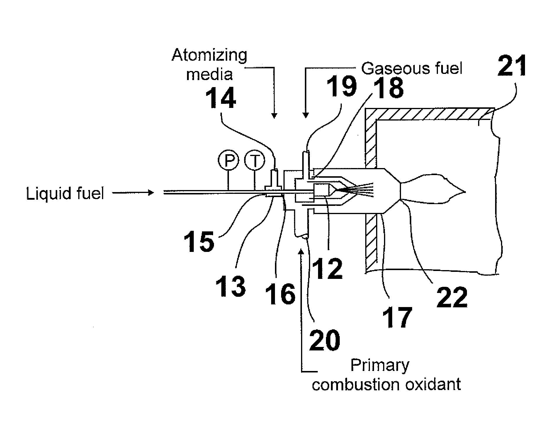
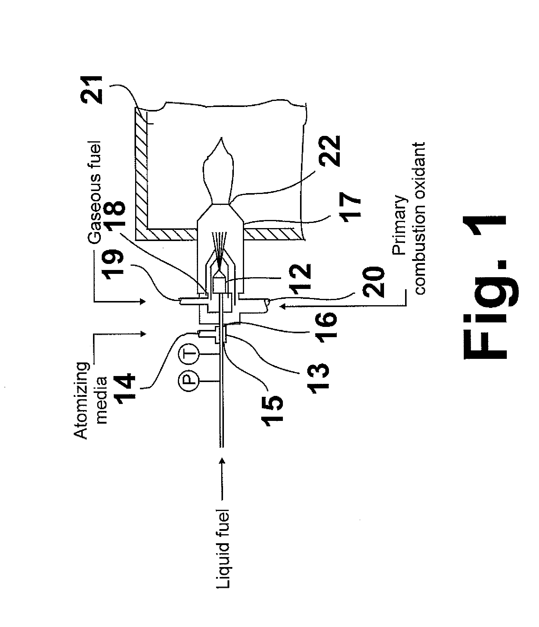
[0026]The invention described herein is a method and system for providing low-NOx combustion of a liquid fuel while maintaining high efficiency and substantially avoiding soot formation. As used herein, the term “low-NOx” refers to NOx emission levels less than about 20 ppmv for liquid fuels and less than about 5 ppmv for gaseous fuels. The invention comprises the following features, which will be discussed in more detailed herein below: atomization of liquid fuel, partial liquid fuel evaporation, premixing of gaseous fuel or vapors of liquid fuel with primary combustion oxidant, oxidant-staged combustion, and forced internal flue gas recirculation. As used herein, the terms “atomizing” and “atomization” refer to a process whereby a liquid is transformed into a plurality of droplets and the terms “evaporating”, “vaporizing”, “evaporation”, and “vaporization” refer to a process in which a liquid is converted to a vapor.

[0027]FIG. 1 shows a combustion apparatus for combustion of a liq...


PUM


Abstract

A method and apparatus for combustion in which a pressurized preheated liquid fuel is atomized and a portion thereof flash vaporized, creating a mixture of fuel vapor and liquid droplets. The mixture is mixed with primary combustion oxidant, producing a fuel/primary oxidant mixture which is then injected into a primary combustion chamber in which the fuel/primary oxidant mixture is partially combusted, producing a secondary gaseous fuel containing hydrogen and carbon oxides. The secondary gaseous fuel is mixed with a secondary combustion oxidant and injected into the second combustion chamber wherein complete combustion of the secondary gaseous fuel is carried out. The resulting second stage flue gas containing very low amounts of NOx is then vented from the second combustion chamber.

Description

[0001]The U.S. Government has a paid-up license in this invention and the right in limited circumstances to require the patent owner to license others on reasonable terms as provided for by the terms of Contract No. DE-FG36-05GO15189 awarded by the U.S. Department of Energy.BACKGROUND OF THE INVENTION[0002]1. Field of the Invention[0003]This invention relates to a method and apparatus for combustion of liquid fuels or mixtures of liquid and gaseous fuels. In one aspect, this invention relates to emissions produced by the combustion of liquid fuels and mixtures of liquid and gaseous fuels. In one aspect, this invention relates to the control of NOx emissions resulting from the combustion of liquid fuels and mixtures of liquid and gaseous fuels. In one aspect, this invention relates to a method and apparatus for dual-fuel combustion, i.e., combustion of a mixture of liquid and gaseous fuels. In one aspect, this invention relates to dual-fuel combustion in boilers for steam and power g...

Claims


Application Information

Patent Timeline
IPC IPC(8): F23C6/04F23K5/22F23C1/08F23C9/06F23D11/44F23N1/02
CPCF23K5/22F23N1/02F23C1/08F23C6/04F23C9/06F23D11/44F23D2204/10F23D14/58F23D17/002F23C2201/401F23C2900/06041F23D11/10F23D11/38
Inventor GARD, VINCENTCHOJNACKI, DENNIS A.RABOVITSER, IOSEPH K.
Owner GAS TECH INST
Why Eureka
Try Eureka