Strand for saw wire and manufacturing method thereof

a technology of saw wire and manufacturing method, which is applied in the direction of manufacturing tools, furnaces, heat treatment equipment, etc., can solve the problems of reducing yield, reducing yield, and high cost of sic single crystal, so as to suppress a breakage, high strength, and high breakage resistance

Inactive Publication Date: 2012-12-20
NIPPON STEEL CORP
View PDF1 Cites 18 Cited by
  • Summary
  • Abstract
  • Description
  • Claims
  • Application Information

AI Technical Summary

Benefits of technology

[0097]According to the present invention, it is possible to realize both of high strength and high breakage resistance. Therefore, when a saw wire is formed by using the strand for saw wire, it is possible to suppress a breakage at a time of cutting a material to be cut while reducing a cutting cost.

Problems solved by technology

Sapphire and SiC single crystal are more expensive than Si single crystal.
However, when cutting of a material to be cut is performed by using a saw wire with a small wire diameter, the saw wire is likely to be broken during the cutting.
When the saw wire is broken during the cutting, the cutting has to be stopped at that point, which results in reducing the yield.
Therefore, the more expensive the material to be cut, the higher the necessity for suppressing the breakage of the saw wire.

Method used


Image

  • Strand for saw wire and manufacturing method thereof
  • Strand for saw wire and manufacturing method thereof

Examples


example

[0166]Next, experiments conducted by the present inventors will be described. Conditions and so on in these experiments are only examples adopted for confirming feasibility and effects of the present invention, and the present invention is not limited to these examples.

[0167](First Experiment)

[0168]In a first experiment, first, steel billets having chemical components presented in Table 1 (steels No. 1A to 1W) were subjected to hot rolling, and then cooled at cooling rates presented in Table 2, thereby obtaining hot-rolled wire rods with diameters presented in Table 2 (tests No. 1-1 to No. 1-44). Finish rolling in the hot rolling was conducted within a temperature range of 920° C. to 950° C. The cooling rates were controlled through air blasting. Further, by methods described below, a fraction of pearlite structure and a thickness of cementite of each of the hot-rolled wire rods were measured. Results thereof are presented in Table 2.

[0169]In the measurement of the fraction of pearl...


PUM

PropertyMeasurementUnit
tensile strengthaaaaaaaaaa
tensile elongationaaaaaaaaaa
thicknessaaaaaaaaaa

Abstract

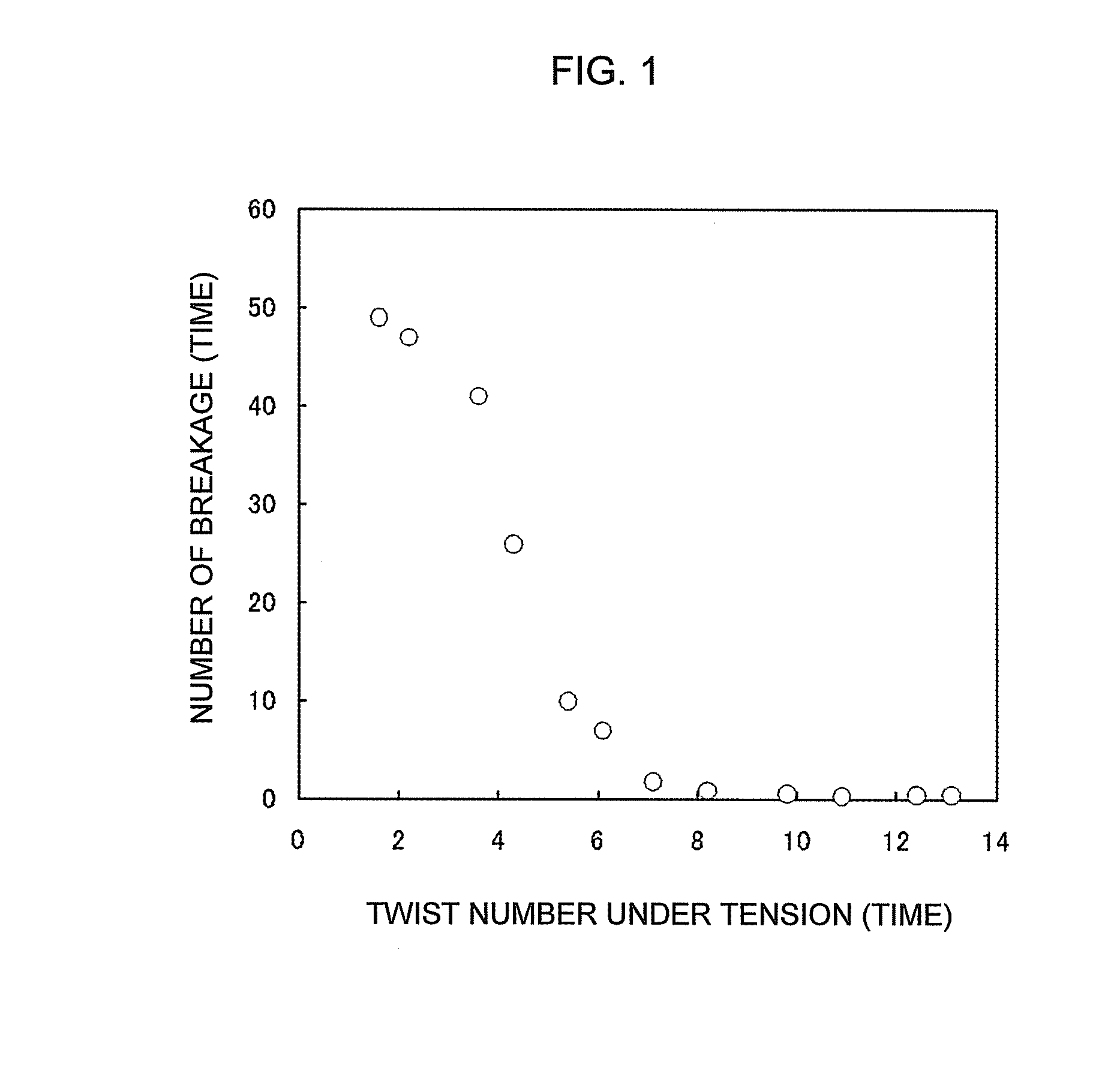
Regarding contents of C, Si, Mn and Cr, a value of parameter P represented by the following (equation 1) is 1000 or more. A metallic structure contains wire-drawn pearlite in an area ratio of 98% or more, a diameter is 0.05 mm to 0.18 mm, a tensile strength is 4000 MPa or more, and a twist number in a twist test in which a grip-to-grip distance is 100 mm, and a tension equal to a tensile strength×a cross-sectional area of wire×0.5 is applied, is 5 or more.P=1098×[C]+98×[Si]−20×[Mn]+167×[Cr]  (equation 1)(in the (equation 1), [C], [Si], [Mn] and [Cr] indicate contents (mass %) of C, Si, Mn and Cr, respectively.)

Description

TECHNICAL FIELD[0001]The present invention relates to a strand for saw wire used for cutting a metallic material, a ceramic material, a semiconductor material and the like, and a manufacturing method thereof.BACKGROUND ART[0002]A saw wire is used for cutting Si single crystal, Si polycrystal, sapphire, SiC single crystal and the like. Further, a piano strand for saw wire, a steel strand for saw wire and the like have been proposed (Patent Literatures 1 and 2). The saw wire is required to have a small wire diameter and high strength.[0003]Further, a strand for steel cord used for reinforcing a tire, a belt and the like is also required to have a small wire diameter and high strength, similar to the saw wire. Further, various strands for steel cords have been proposed (Patent Literatures 3 to 9).[0004]As saw wires, there have been known a free-abrasive saw wire and a fixed-abrasive saw wire. The fixed-abrasive saw wire is formed such that an abrasive such as diamond is fixed on a stra...

Claims


Application Information

Patent Timeline
Patent Type & Authority Applications(United States)
IPC IPC(8): C22C38/34C21D8/06C22C38/24C22C38/20C22C38/22C21D11/00C22C38/40
CPCB23D61/185C21D8/06C21D9/24C21D9/525C22C38/18C22C38/001C22C38/02C22C38/04C21D2211/009
Inventor TARUI, TOSHIMINAKAMURA, KENICHISAKAMOTO, MASASHI
Owner NIPPON STEEL CORP
Why Eureka
Try Eureka