Terahertz-wave generating element, terahertz-wave detecting element, and terahertz time-domain spectroscopy device

a technology of terahertz time-domain spectroscopy and generating elements, which is applied in the direction of optical radiation measurement, instruments, spectrometry/spectrophotometry/monochromators, etc., can solve the problems of achieve the effect of improving the s/n ratio of the terahertz time-domain spectroscopy device and reducing the efficiency of total terahertz generation

Active Publication Date: 2012-12-20
CANON KK
View PDF6 Cites 15 Cited by
  • Summary
  • Abstract
  • Description
  • Claims
  • Application Information

AI Technical Summary

Benefits of technology

[0009]However, in the methods discussed in NPL 1 and NPL 2, light is simply passively irradiated onto the nonlinear optic crystal, and an adjusting unit for performing modulation on the generated terahertz wave is not included. Therefore, an external adjusting unit is required for adjusting the intensity of the terahertz wave. For example, although a rotatable light chopper is generally used when performing synchronous detection, since such a light chopper is of a mechnical type, the modulation speed is several kHz at most, and about 50% of the excitation light is cut. Therefore, the total terahertz generation efficiency is reduced, possibly becoming a hindrance to achieving an improved S / N ratio of the terahertz time-domain spectroscopy device.

Problems solved by technology

Therefore, the total terahertz generation efficiency is reduced, possibly becoming a hindrance to achieving an improved S / N ratio of the terahertz time-domain spectroscopy device.

Method used


Image

  • Terahertz-wave generating element, terahertz-wave detecting element, and terahertz time-domain spectroscopy device
  • Terahertz-wave generating element, terahertz-wave detecting element, and terahertz time-domain spectroscopy device
  • Terahertz-wave generating element, terahertz-wave detecting element, and terahertz time-domain spectroscopy device

Examples


example 1

Practical Example 1

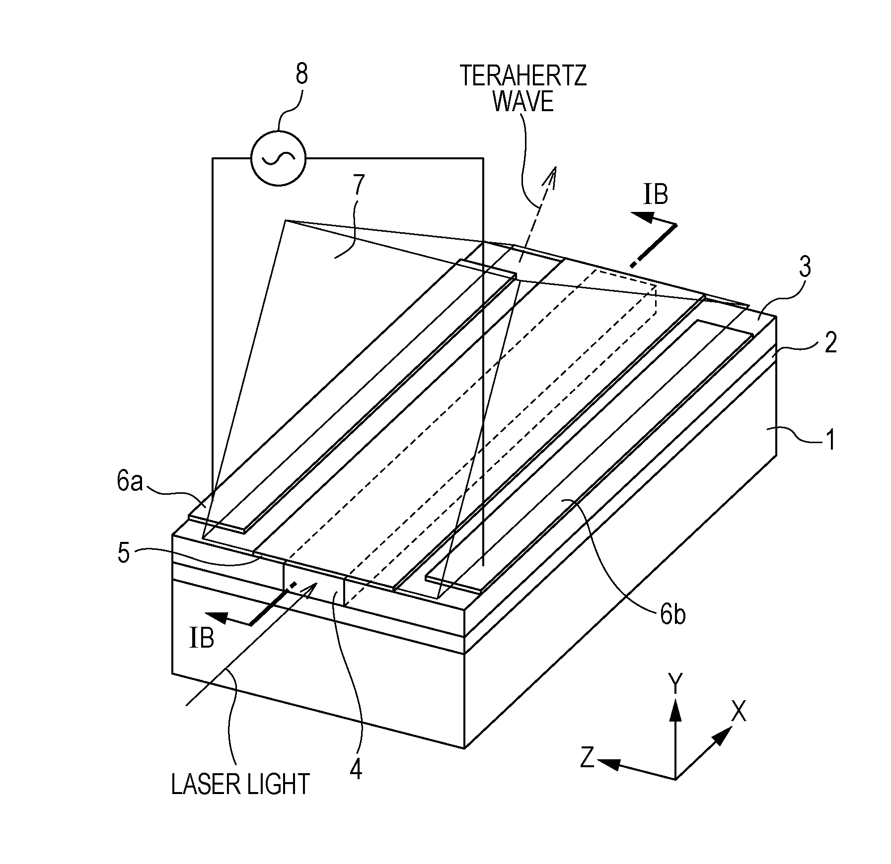
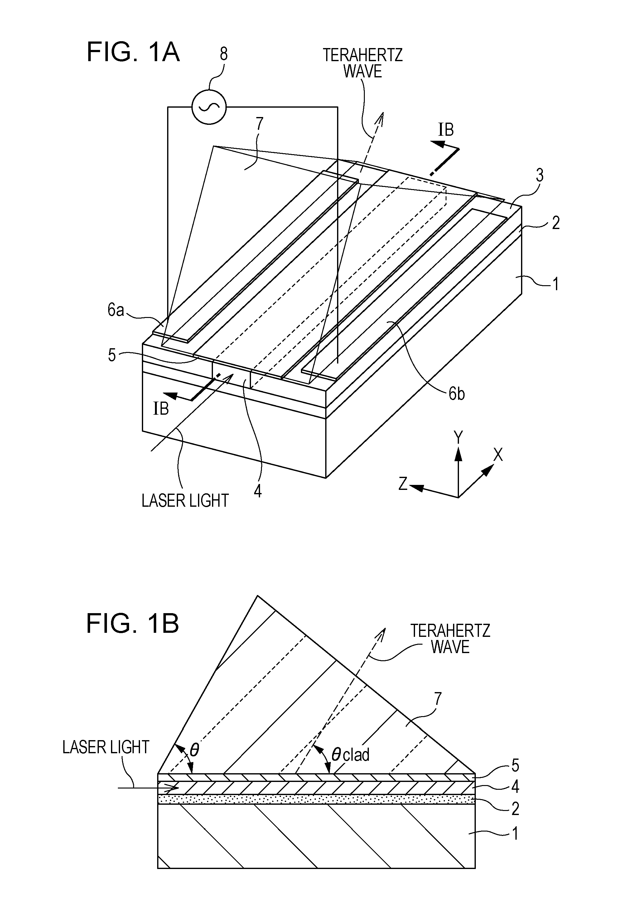
[0039]A detailed practical example 1 corresponding to the first embodiment will now be described. In the element structure shown in FIGS. 1A and 1B in this practical example, an optical adhesive layer 2 having a refractive index n of about 1.5 is formed to a thickness of 3 μm, and a MgO-doped waveguide layer 4 is formed to a thickness of 3.8 μm.

[0040]The thickness of the waveguide layer 4 is determined as follows. First, a maximum frequency fmax of a terahertz pulse (terahertz wave) to be obtained is determined from that terahertz pulse. The maximum frequency fmax corresponds to a maximum frequency when the terahertz pulse to be obtained is Fourier-transformed. Then, the thickness of the waveguide layer 4 is smaller than or equal to half the length of an equivalent wavelength (effective wavelength) within the electro-optic crystal, corresponding to the maximum frequency fmax of the terahertz wave extracted to the space, and a single mode condition corresponding to...


PUM

PropertyMeasurementUnit
refractive indicesaaaaaaaaaa
Cerenkov radiation angleaaaaaaaaaa
angleaaaaaaaaaa

Abstract

A terahertz-wave generating element includes a waveguide including an electro-optic crystal; an optical coupling member that extracts a terahertz wave, which is generated from the electro-optic crystal as a result of light propagating through the waveguide, to a space; and at least two electrodes that cause a first-order electro-optic effect in the electro-optic crystal by applying an electric field to the waveguide so as to change a propagation state of the light propagating through the waveguide. A crystal axis of the electro-optic crystal of the waveguide is set such that the terahertz wave generated by a second-order nonlinear optical process and the light propagating through the waveguide are phase-matched.

Description

TECHNICAL FIELD[0001]The present invention relates to terahertz-wave generating elements that generate terahertz waves including electromagnetic wave components in a frequency range from a millimeter wave band to a terahertz wave band (30 GHz to 30 THz), terahertz-wave detecting elements that detect terahertz waves, and terahertz time-domain spectroscopy devices that use at least one of the above. In particular, the present invention relates to a generating element that includes an electro-optic crystal for generating or detecting an electromagnetic wave including a Fourier component in the aforementioned frequency range by laser light irradiation, and to a tomography device that uses the aforementioned generating element to perform terahertz time-domain spectroscopy (THz-TDS).BACKGROUND ART[0002]In recent years, non-destructive sensing techniques using terahertz waves have been developed. As an application field of electromagnetic waves in this frequency band, there is a technique ...

Claims


Application Information

Patent Timeline
Patent Type & Authority Applications(United States)
IPC IPC(8): G02F1/035G01J3/42G01J3/28G01N21/35G01N21/3586G02F1/365H01S1/02
CPCG01N21/3586G01N21/4795G02F2203/13G02F1/395G02F1/0356G02F1/3544G02F1/377G02F1/3546G02F1/374G01J3/0216G01J3/42G01N2201/06113
Inventor OUCHI, TOSHIHIKO
Owner CANON KK
Why Eureka
Try Eureka