[0007]In accordance with the present application, data center network architectures, systems, and methods are disclosed that can reduce the cost and complexity of data center networks. Such data center network architectures, systems, and methods employ optical nodes utilizing
hybrid spatial division multiplexing (SDM) /
wavelength division
multiplexing (WDM) shifting channel plans on paired optical ports, which can be connected in a variety of physical cabled network topologies, including, but not limited to, physical rings and physical 2-dimensional and higher dimensional toruses. The combination of a selected physical topology and a selected
hybrid SDM / WDM shifting channel plan produces a switching topology with increased
interconnection density and reduced
diameter and link utilization, resulting in reduced latency and latency
skew. The optical nodes can include
multicast / broadcast capable circuit switches, such as electrical cross-point or electrical cross-bar switches, to increase the functionality of the optical nodes and the network in which the optical nodes are deployed, allowing capacity to be shifted and switch hop counts to be reduced based on network traffic, application requirements, and / or deployment requirements. The network may be employed as a replacement for a multitude of top-of-rack switches in the access layer, thereby reducing the network requirements of the aggregation layer and the core layer. Alternatively, the network may be employed as a replacement for a multitude of aggregation switches and / or core switches, thereby reducing the network requirements on the aggregation layer, the core layer, and the access layer.
[0012]Further, a subset of the four (4) 10 GbE component signals may be provided for direct attach links, and the remainder of the 10 GbE component signals may be provided for
downlink transmission, by suitably connecting the 10 GbE component signals to the transceivers or the
packet switch, respectively. It is noted that, at any given optical node, there may be more transceivers than uplink ports, depending upon the hardware configuration of the optical node, and whether or not any user connection ports are configured to be direct attach, thereby enabling terminated optical signals to be connected by the circuit switch without disrupting any of the optical node's uplinks.
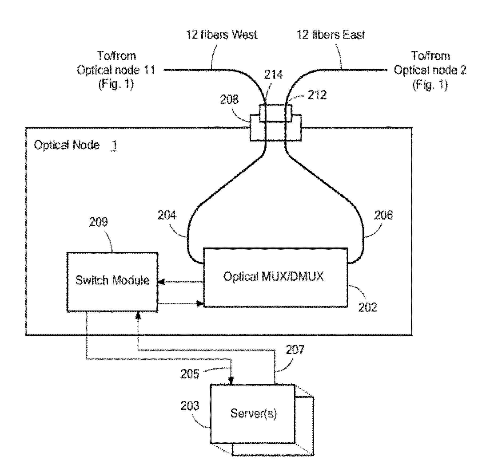
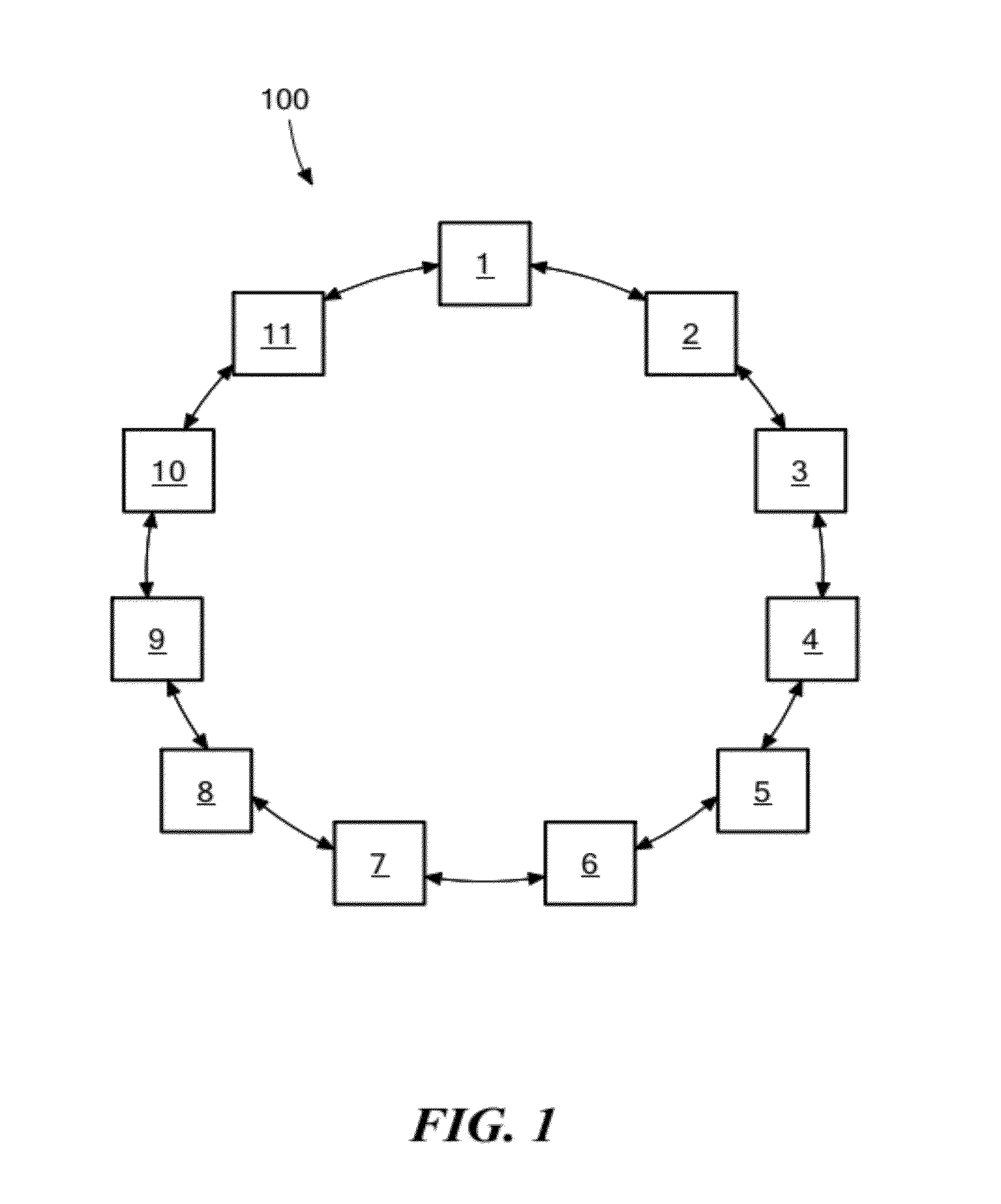
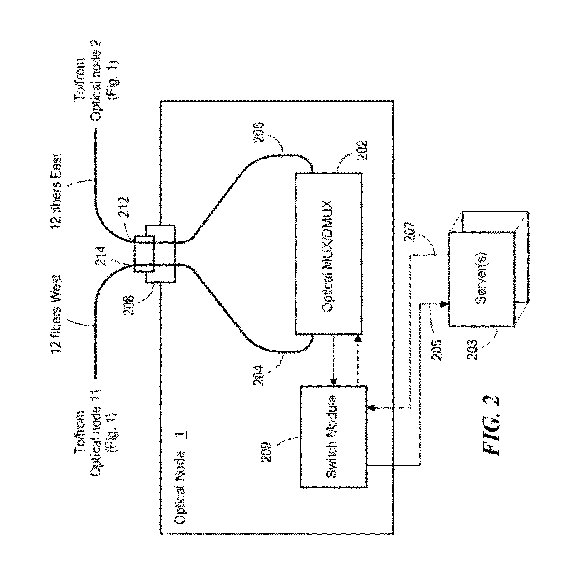
[0028]A plurality of optical nodes implementing various channel plans can be connected in an optical network such that optical ports are connected through a paired optical port to other optical ports that share the same channel plan. For example, optical nodes, all of degree-2, can be logically laid out in a ring, and each optical node can be connected to its two neighboring optical nodes by a plurality of fibers, connecting the East port of the optical node to the West port of one of its neighboring optical nodes, and connecting the West port of the optical node to the East port of its other neighboring optical node. In an exemplary aspect, each type of optical port, e.g., the West port or the East port, is keyed to allow physical connection to its East or West port pair on another optical node. In another exemplary aspect, there is no physical distinction between the East and West ports. In a further exemplary aspect, each optical node is configured to implement a common East / West SDM / WDM shifting channel plan and an identical West / East SDM / WDM shifting channel plan, and the switching topology is a chordal
ring network having a reduced
fiber and / or
wavelength count, allowing the use of less costly optical transceivers and add / drop multiplexers.
[0029]For optical nodes that include a circuit switch, the chords of the chordal
ring network can be reconfigured by effectively attaching two or more chords to produce a chord of increased length.
[0039]In still another aspect, low latency and low latency skew multicasting and
broadcasting can be achieved by configuring the circuit switches of a plurality of optical nodes to establish duplex uplinks from a source or origin
packet switch to a set of primary destination packet switches, using a plurality of the source
packet switch's uplink ports and simplex connections from the same source packet switch and uplink ports to a plurality of secondary packet switches, with one or more circuit switches establishing a simplex multicast or broadcast connection from one of its input ports to a plurality of its output ports, thereby enabling data multicasting and
broadcasting from a
server connected to the source packet switch to a plurality of servers connected to the same packet switch and / or different packet switches. In an exemplary aspect, the transmitting uplink ports on the secondary set of destination packet switches are muted. In another exemplary aspect, the transmitting uplink ports on the secondary set of destination packet switches are not muted, but
data transmission is disabled by the circuit switches connected to the secondary transmitting uplink ports. In still another exemplary aspect, the transmitting uplink ports on one or more of the secondary packet switches are enabled and employed in separate multicast or broadcast communications. In a further aspect, the plurality of optical nodes are on an optical ring network, one of the destination packet switches is the source packet switch, and an outbound
signal from an uplink of the source packet switch is either looped back at that switch's circuit switch onto its
receiver uplink port, or routed through the network, for example, by routing the outbound
signal around the ring so that it connects back on the source packet switch uplink port, thereby establishing the duplex connection. For example, in a physical ring network, a duplex connection can be established from the source packet switch to itself (using two uplink ports connected through the network), and the outbound
signal can be dropped at a plurality of intermediate packet switches to establish multicast or broadcast simplex communications from the source packet switch to the destination packet switches.
[0040]By employing a passive shift strategy for the fibers at each optical node, combined with a fixed and passive
wavelength add / drop scheme, 2-dimensional as well as higher dimensional chordal ring networks can be constructed using a reduced number of communications channels (e.g., fibers, wavelengths, time slots). The optical nodes can be configured to be substantially identical to one another. Further, each optical node can be configured to include a circuit switch to enable dynamic configuration of network chords for tailoring the
network topology to the network traffic, reducing the network
diameter, and / or increasing the density of the
network topology. Each optical node can also include an electrical
Ethernet packet switch to enable a fully integrated, layer 0 / 1 / 2 / 3 configurable, switching network with reduced fiber
interconnection complexity, WDM hardware requirements, circuit switch size, packet switch size, and
processing requirements. Higher degree physical topologies as well as alternate topologies can also be employed. In addition, the multi-fiber bundles can be keyed to reduce fiber cabling errors.

