
Method of forming memory cell access device

a memory cell and access device technology, applied in semiconductor devices, diodes, electrical apparatuses, etc., can solve the problems of unacceptably high off current of diodes having both regions made of doped polysilicon, difficult peripheral circuitry of bipolar junction transistors with cmos, etc., to achieve small leakage current and improve memory operation.

Active Publication Date: 2012-12-27
IBM CORP +1
View PDF0 Cites 54 Cited by
  • Summary
  • Abstract
  • Description
  • Claims
  • Application Information

AI Technical Summary

Benefits of technology

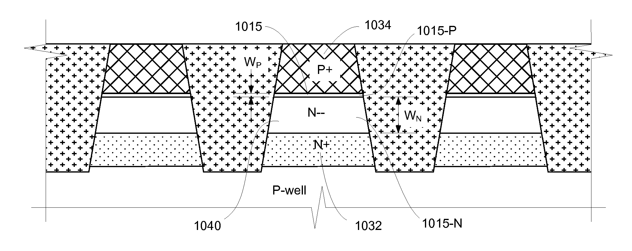
[0015]In some embodiments a region having a lower concentration of doping may be situated between the first and second doped regions at the p-n junction, having a conductivity type P− or N−−, for example. This may provide a diode having a smaller leakage current in the off condition, allowing for improved memory operation.

Problems solved by technology

Bipolar junction transistors (BJT) can provide larger current drive than field effect transistors, but the integration of bipolar junction transistors with CMOS peripheral circuitry is difficult and results in highly complex designs and manufacturing processes.
However, diodes having both regions made of doped polysilicon may have an unacceptably high off current.
Diodes having both regions made of doped single-crystal silicon may provide a suitably low off current, but processes for making a diode having both regions made of doped single-crystal silicon are complex.
However, such structures do not completely solve the problem of high off-current due to the polysilicon terminal, and have not been proposed for memory cell access devices.

Method used


Image

  • Method of forming memory cell access device
  • Method of forming memory cell access device
  • Method of forming memory cell access device

Examples


Embodiment Construction

[0048]The invention will now be described in further detail by reference to the drawings, which illustrate alternative specific embodiments and methods. The drawings are diagrammatic, showing features of the embodiments and their relation to other features and structures, and are not made to scale. For improved clarity of presentation, in the figures illustrating various embodiments, elements corresponding to elements shown in other drawings are not all particularly renumbered, although they are all readily identifiable in all the figures. Also for clarity of presentation certain features are not shown in the figures, where not necessary for an understanding of the invention. It is to be understood that there is no intention to limit the invention to the specifically disclosed embodiments and methods but that the invention may be practiced using other features, elements, methods and embodiments. Preferred embodiments are described to illustrate the present invention, not to limit it...


PUM


Abstract

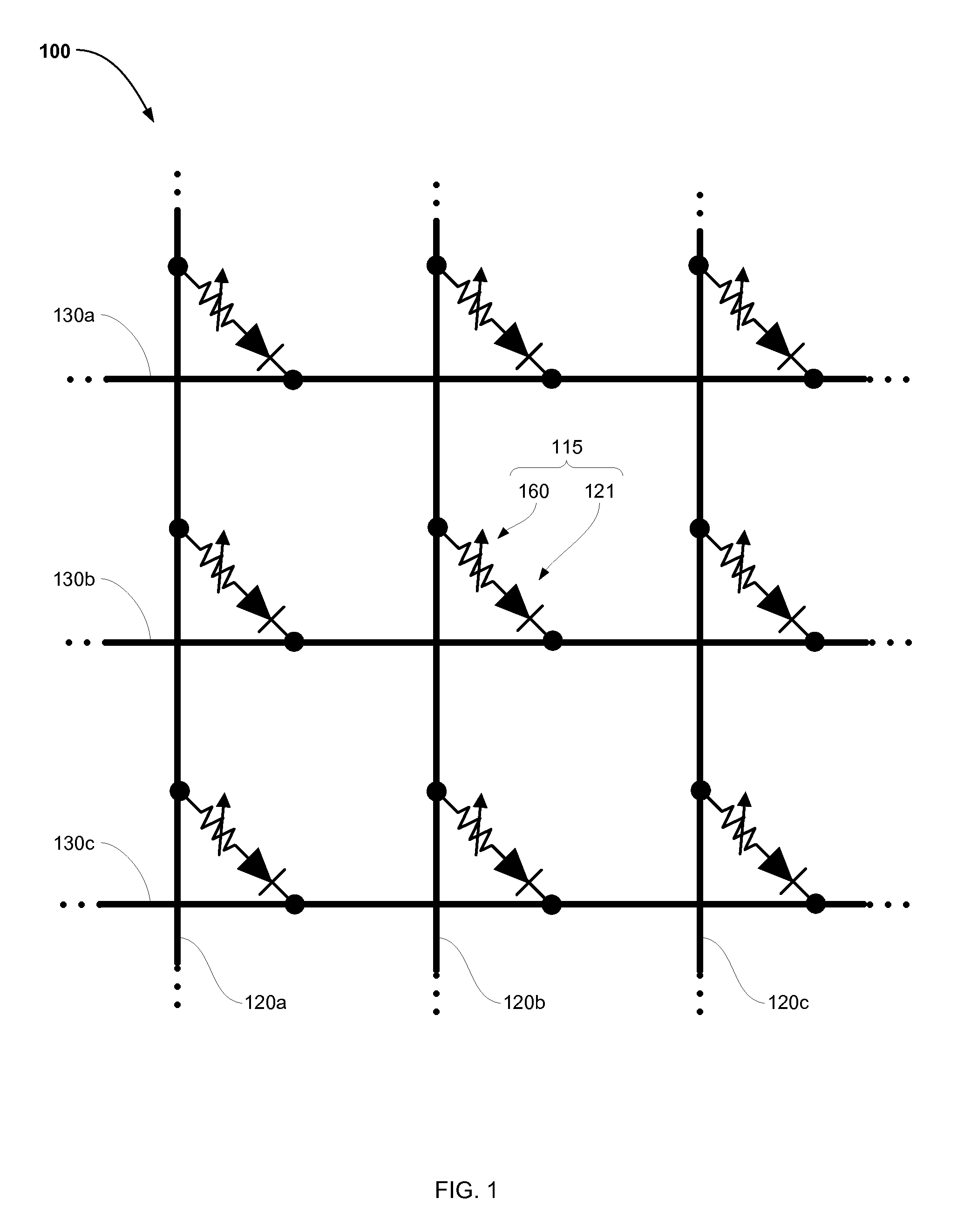
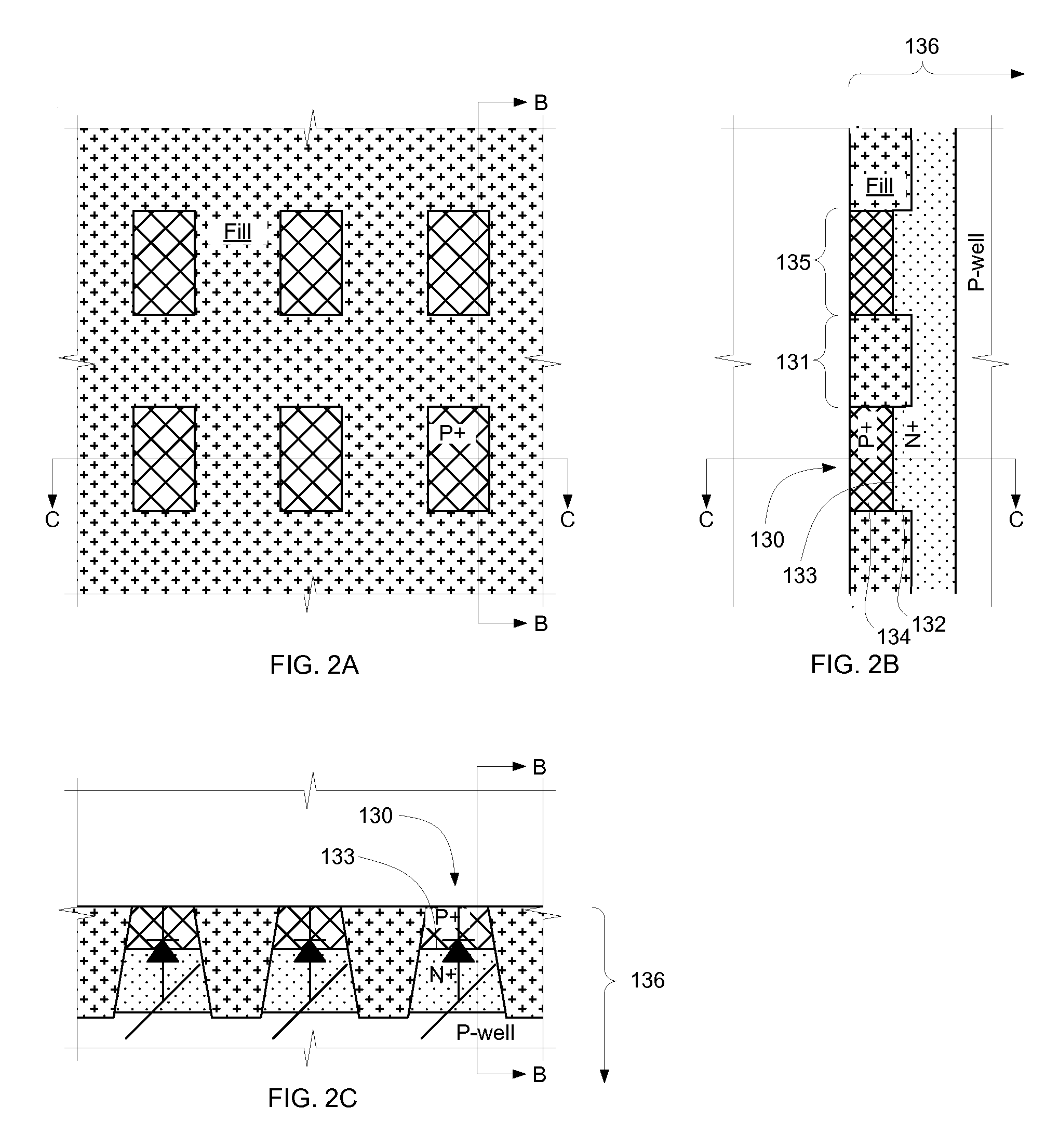
A memory device includes an access device including a first doped semiconductor region having a first conductivity type, and a second doped semiconductor region having a second conductivity type opposite the first conductivity type. Both the first and the second doped semiconductor regions are formed in a single-crystalline semiconductor body, and define a p-n junction between them. The first and second doped semiconductor regions are implemented in isolated parallel ridges formed in the single-crystal semiconductor body. Each ridge is crenellated, and the crenellations define semiconductor islands; the first doped semiconductor region occupies a lower portion of the islands and an upper part of the ridge, and the second doped semiconductor region occupies an upper portion of the islands, so that the p-n junctions are defined within the islands.

Description

PARTIES TO A RESEARCH AGREEMENT[0001]International Business Machines Corporation, a New York corporation and Macronix International Corporation, Ltd., a Taiwan corporation, are parties to a Joint Research Agreement.BACKGROUND[0002]1. Field of the Invention[0003]This invention relates to high density memory devices based on phase change based memory materials, including chalcogenide based materials and other programmable resistive materials, and to methods for manufacturing such devices.[0004]2. Description of Related Art[0005]Phase change based memory materials, such as chalcogenide based materials and similar materials, can be caused to change phase between an amorphous state and a crystalline state by application of electrical current at levels suitable for implementation in integrated circuits. The generally amorphous state is characterized by higher electrical resistivity than the generally crystalline state, which can be readily sensed to indicate data. These properties have ge...

Claims


Application Information

Patent Timeline
IPC IPC(8): H01L21/762H01L27/08B82Y99/00
CPCH01L27/1021H01L27/101
Inventor LAI, ERH-KUNLUNG, HSIANG-LANKIEWRA, EDWARD
Owner IBM CORP
Learn More