High sensitivity gps/gnss receiver

Inactive Publication Date: 2012-12-27
MAYFLOWER COMM CO INC
View PDF36 Cites 30 Cited by
  • Summary
  • Abstract
  • Description
  • Claims
  • Application Information

AI Technical Summary

Benefits of technology

[0010]In one embodiment, the PDA determines the weights applied to the measurement updates in the navigation filter, thereby guarding against the use of spurious measurements and stabilizing the navigation solution under noisy conditions.
[0011]In one embodiment, the HSGR achieves improved GPS tracking sensitivity in part through the effect of vector tracking, wherein the PDA-augmented navigation filter state, conventional tracking loop filter information, and satellite ephemeris information from all the tracked satellites are combined to form the carrier and code Digital Controlled Oscillator (DCO) commands for exploiting the correlations between the tracked satellite signals. The correlation between the satellite signals originates from that part of the relative motion between the different tracked satellites and the GPS receiver that is due to the receiver's motion alone. Vector tracking (VT) allows the HSGR to track all the satellites cooperatively. The state information

Problems solved by technology

The traditional approach fails to fully exploit any useful correlations between the GPS signals in the tracking channels.
For example, since the Global Positioning System data bit time is 20 ms, the coherent integration of its signals is ordinarily limited to this 20 ms period, hence limiting the receiver processing gain.
Obtaining coherent integration periods longer than the data bit time is only possible, however, where the receiver is aided by a

Method used


Image

  • High sensitivity gps/gnss receiver
  • High sensitivity gps/gnss receiver
  • High sensitivity gps/gnss receiver

Examples


Example

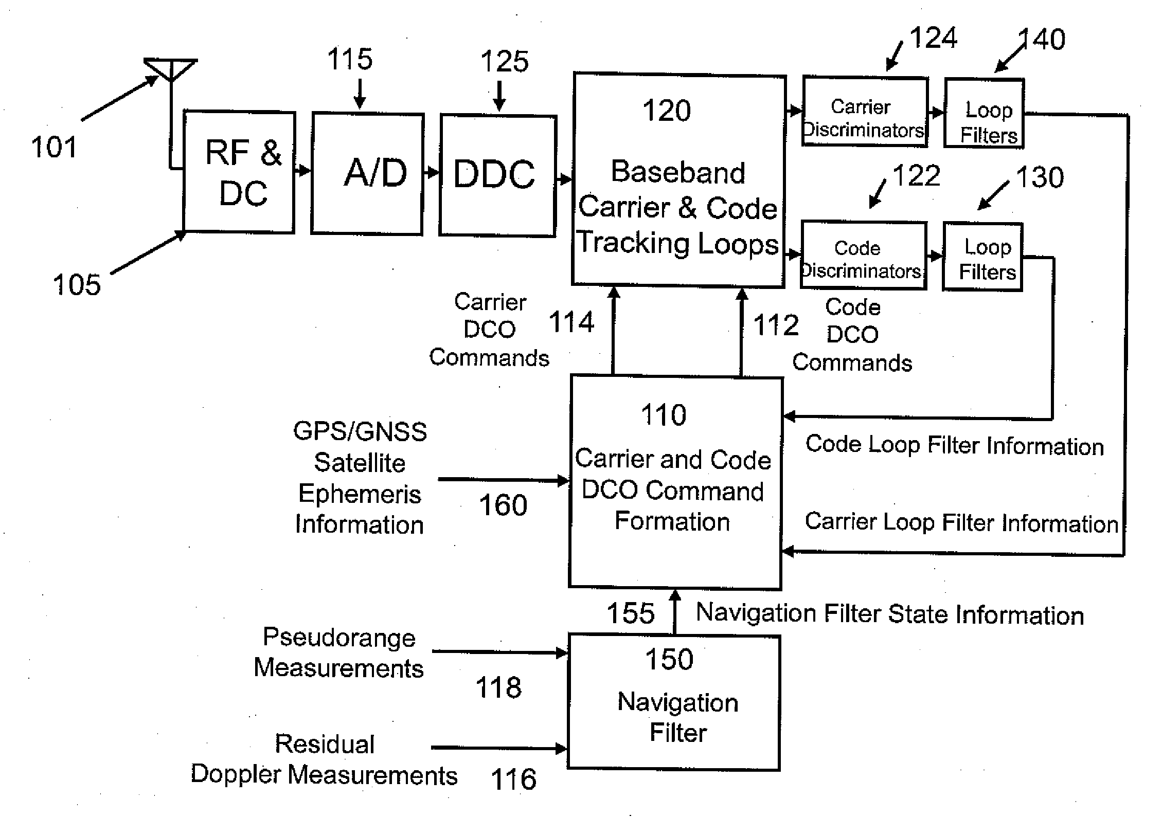
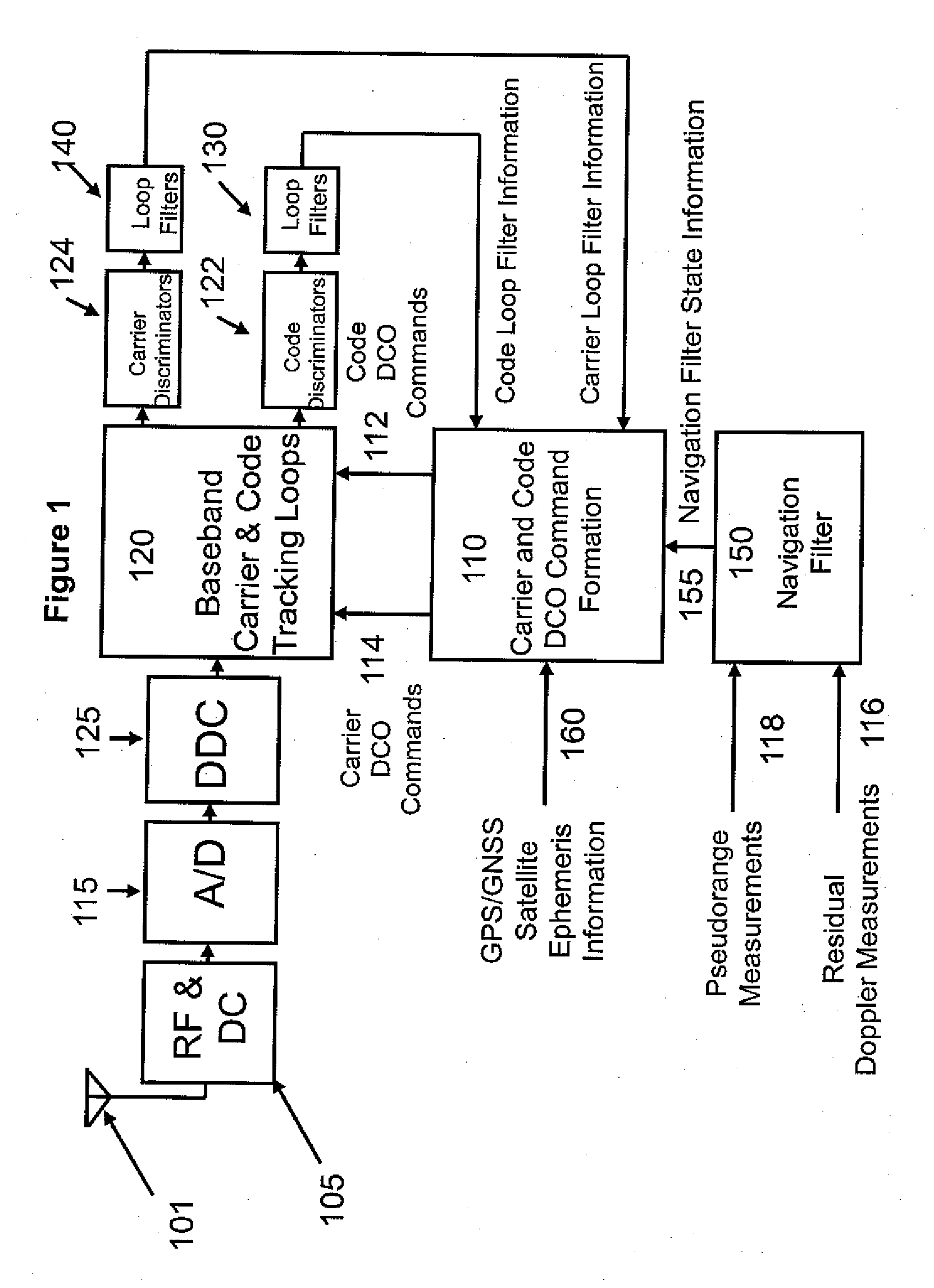
[0021]FIG. 1 presents an overview block diagram of the High Sensitivity GPS Receiver (HSGR). It shows a typical GPS receiver RF front end 105 for GPS signals received at antenna 101. The received signal is downconverted to an intermediate frequency and digitized using an Analog-to-Digital (A / D) converter 115. The digitized signal is processed with a Digital Down Converter (DDC) 125, whose output signal is provided at baseband to the Digital Signal Processor (DSP) 120 for code and carrier tracking. The Digital Controlled Oscillator (DCO) commands 112 and 114 used in the DSP 120 for code and carrier tracking, respectively, are derived 110 using information from the conventional code loop filter 130 and carrier loop filter 140, the navigation filter state 155 output by the navigation filter 150, and the satellite ephemeris data 160 received by the HGSR from the satellite (SV).

[0022]A. Navigation Filter State Model and the Navigation Filter

[0023]The true HSGR navigation state (position,...


PUM


Abstract

The GPS/GNSS receiver and method disclosed herein improves the GPS/GNSS receiver tracking sensitivity for detecting low signal-to-noise (SNR) GPS/GNSS signals through improved vector tracking, multibit correlation, improved extended range code-phase discrimination, and discrimination and navigation filter measurement via Probabilistic Data Association, individually or in combination. The solution is achieved without any external data aiding, such as from an inertial measurement unit, other wireless infrastructure source, or communication of GPS/GNSS satellite vehicle (SV) subframe data to the GPS/GNSS receiver over a data link.

Description

[0001]This application claims the benefit of U.S. Provisional Application No. 61 / 571,312 filed on Jun. 24, 2011.[0002]The present invention was made with U.S. Government support under Contract No. HM1582-09-C-0012 awarded by the National Geo-Spatial Intelligence Agency. The U.S. Government has certain rights to this invention.FIELD OF THE INVENTION[0003]This invention relates to Global Positioning System and other Global Navigation Satellite System (GPS / GNSS) receivers. More particularly, the present invention is in the technical field of GPS / GNSS satellite signal tracking using a GPS / GNSS receiver. More particularly, the present invention is in the technical field of reliable, high sensitivity GPS / GNSS signal tracking of low signal-to-noise ratio (SNR) GPS / GNSS signals using a GPS / GNSS receiver.BACKGROUND OF THE INVENTION[0004]The tracking of GPS / GNSS signals (i.e. GPS or other GNSS signals, hereinafter commonly referred to as “GPS signals”) using a GPS / GNSS receiver (i.e. GPS or o...

Claims


Application Information

Patent Timeline
IPC IPC(8): G01S19/29G01S19/30
CPCG01S19/243G01S19/30G01S19/29G01S19/246
Inventor VANDER VELDE, WALLACE EARLDIMOS, GEORGELUO, JIANHUIZAROWSKI, CHRISTOPHER J.
Owner MAYFLOWER COMM CO INC
Why Eureka
Try Eureka