Light emitting device

a light emitting device and light technology, applied in the field can solve the problems of disadvantageous degradation of heat dissipation of fluorescent members, increased consumption power, complicated configuration, etc., and achieve the effects of enhancing the efficiency of light emission of light emitting devices, enhancing the dissipation of heat, and increasing the rate of absorbing excitation ligh

Active Publication Date: 2013-01-03
SHARP FUKUYAMA LASER CO LTD
View PDF6 Cites 11 Cited by
  • Summary
  • Abstract
  • Description
  • Claims
  • Application Information

AI Technical Summary

Benefits of technology

[0011]The present invention is made to solve the problem described above; an object of the present invention is to provide a light emitting device that can enhance the efficiency of light emission by enhancing the dissipation of heat produced by a fluorescent body and the rate of absorbing excitation light.
[0016]In the light emitting device according to the present invention and configured as described above, a coating material which adheres the fluorescent body layer is arranged on the surface of the fluorescent body layer. In this configuration, the fluorescent body layer in which the particles of the fluorescent body are deposited on the substrate are adhered with the coating material, and thus the particles of the fluorescent body are prevented from coming off.
[0023]In the present invention, since the fluorescent member has the fluorescent body layer in which the particles of the fluorescent body are deposited on the substrate formed with the highly heat conductive member, the fluorescent body layer has the fluorescent body at a high density and is formed to be thin. Thus, it is possible to enhance the dissipation of the heat produced by the fluorescent body and increase the rate of absorbing the excitation light. It is therefore possible to enhance the efficiency of light emission of the light emitting device and to prevent variations in chromaticity caused by temperature quenching of a plurality of fluorescent bodies that emit light of different colors.
[0024]In the present invention, since the dispersion step of dispersing the particles of the fluorescent body in the dispersion medium and the fluorescent body layer formation step of forming the fluorescent body layer by depositing the particles of the fluorescent body dispersed in the dispersion medium on the substrate by the electrophoresis method or the precipitation method are provided, it is possible to easily form the fluorescent body layer where the particles of the fluorescent body are deposited on the substrate.

Problems solved by technology

Here, when the thickness of the sealant of the fluorescent member is increased so as to enhance the rate of absorbing the fluorescent member, and thus a content of the fluorescent member is increased, since the fluorescent body on the emission surface side is separated from the substrate, the heat dissipation of the fluorescent member is disadvantageously degraded.
Although, in the conventional fluorescent member described above, the fluorescent member is moved to change the position of application of the excitation light, and thus the increase in the temperature of the fluorescent body is reduced, a drive portion for moving the position of the application is required, with the result that disadvantageously, the consumption power is increased and its configuration is complicated.
On the other hand, since the particles of the fluorescent body are dispersed into the sealant, it is difficult to increase the content of the fluorescent body while the sealant is thin.

Method used


Image

  • Light emitting device
  • Light emitting device
  • Light emitting device

Examples


Embodiment Construction

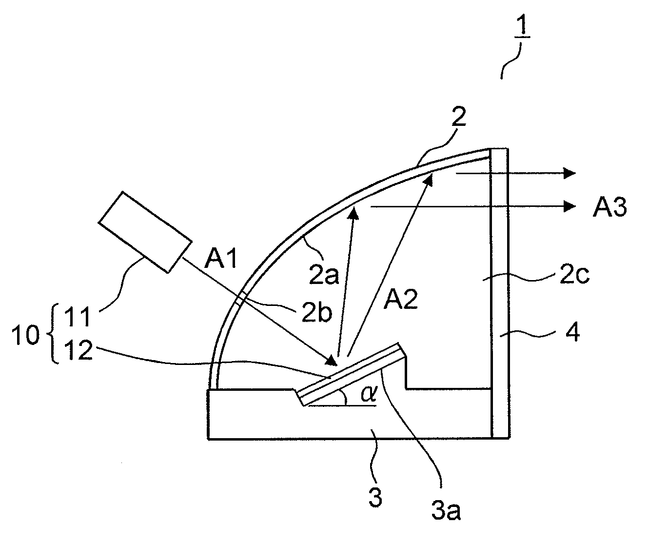
[0032]An embodiment of the present invention will be described below with reference to accompanying drawings. FIG. 1 is a side cross-sectional view showing a head light of an automobile including a light emitting device according to the embodiment. The head light 1 includes the light emitting device 10, a reflective mirror 2, an attachment member 3 and a filter member 4. The light emitting device 10 includes a light source 11 and a fluorescent member 12.

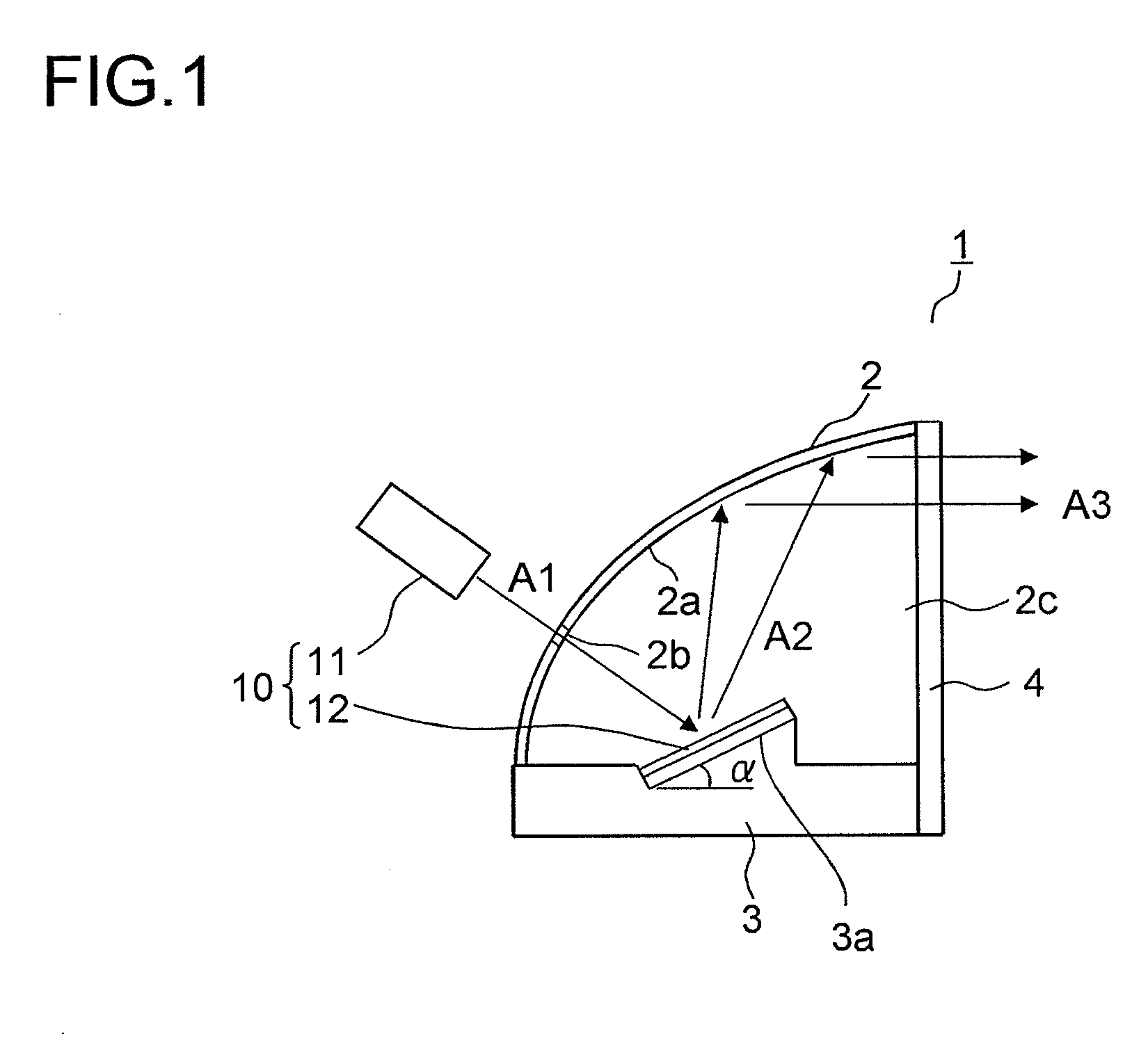
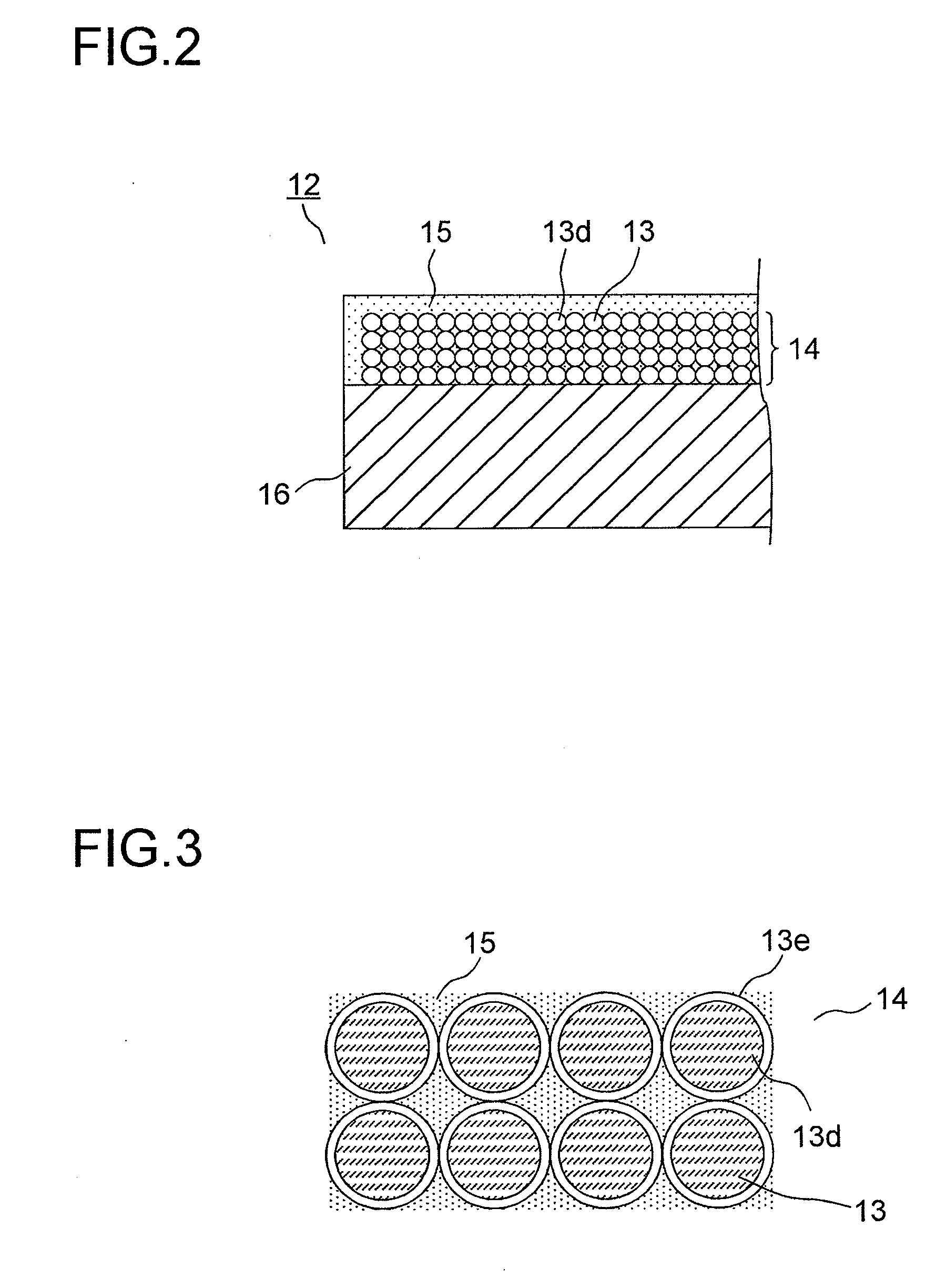
[0033]The light source 11 emits laser light that is near-ultraviolet light having a light emission peak in a wavelength range of 350 nm to 420 nm. The fluorescent member 12, the details of which will be described later, has fluorescent bodies 13 (see FIG. 2), and emits fluorescent light whose wavelength is converted by being excited by light emitted from the light source 11.

[0034]The fluorescent member 12 includes three types of fluorescent bodies 13, and they convert the near-ultraviolet excitation light into red light, green light ...


PUM


Abstract

In a light emitting device (10) includes a light source (11) which emits near-ultraviolet laser light and a fluorescent member (12) which includes a fluorescent body (13) that is excited by the light emitted from the light source (11) so as to emit light, the fluorescent member (12) includes a substrate (16) which is formed with a highly heat conductive member and a fluorescent body layer (14) in which particles (13d) of the fluorescent body (13) are deposited on the substrate (16).

Description

[0001]This application is based on Japanese Patent Application No. 2011-146443 filed in Japan on Jun. 30, 2011, the contents of which are hereby incorporated by reference.BACKGROUND OF THE INVENTION[0002]1. Field of the Invention[0003]The present invention relates to a light emitting device that excites a fluorescent body with near-ultraviolet light and emits light.[0004]2. Description of the Related Art[0005]A conventional light emitting device is disclosed in JP-A-2010-86815. This light emitting device includes a light source and a plurality of fluorescent members. The fluorescent members have fluorescent bodies that are excited by excitation light to emit red light, blue light and green light, respectively, and are provided on a heat transmission member. The light source is formed with a light emitting diode or a laser diode, and emits, as the excitation light, ultraviolet light having a wavelength shorter than the band of the wavelength of the light emitted by the fluorescent bo...

Claims


Application Information

Patent Timeline
Patent Type & Authority Applications(United States)
IPC IPC(8): F21V9/00H01J9/22
CPCH01L33/507H01S5/005H01S3/005H01L33/644F21Y2115/10F21K9/64F21Y2115/30H01S5/0087
Inventor MAEMURA, YOSUKETAKAHIRA, YOSHIYUKITAKAHASHI, KOJI
Owner SHARP FUKUYAMA LASER CO LTD
Why Eureka
Try Eureka