Foamed electrical wire and a method of producing the same

Active Publication Date: 2013-01-17
ESSEX FURUKAWA MAGNET WIRE LLC
View PDF16 Cites 26 Cited by
  • Summary
  • Abstract
  • Description
  • Claims
  • Application Information

AI Technical Summary

Benefits of technology

[0018]The foamed electrical wire of the present invention is excellent in dielectric breakdown voltage even the foaming magnification is increased, and also excellent in partial discharge resistance by a low dielectric constant property due to foaming.
[0019]Specifically, the foamed electrical wire of the present invention containing a foamed insulating layer composed of a thermoplastic resin that is a crystalline thermoplastic resin having a melting point of 150° C. or more or a non-crystalline thermoplastic resin having a glass transition temperature of 150° C. or more, in which the average bubble diameter of the foamed insulating layer is 5 μm or less, can provide an effect that the dielectric breakdown voltage is not decreased. Although the upper limit value of the melting point of the above-mentioned crystalline thermoplastic resin or the glass transition temperature of the non-crystalline thermoplastic resin is not specifically limited, it is generally 400° C. or less. Although the lower limit value of the average bubble diameter of the above-mentioned foamed insulating layer is not specifically limited, it is generally 0.01 μm or more.
[0020]Furthermore, by using a foamed insulating layer having an effective dielectric constant of 2.5 or less, more preferably 2.0 or less, or by using a thermoplastic resin having a dielectric constant of 4.0 or less, more preferably 3.5 or less, an effect of remarkably improving a partial discharge inception voltage can be obtained. The foamed electrical wire of the present invention containing a foamed insulating layer composed of a crystall

Problems solved by technology

In particular, an output pulse occurred due to a high-speed switching device, such as an IGBT, is high in steep voltage rise.
Accordingly, even if a connection cable is short, the surge voltage is high, and voltage decay due to the connection cable is also low.
However, when the thickness of the insulating layer is increased, the resultant insulated wire becomes thicker, and as a result, size enlargement of electrical e

Method used


Image

  • Foamed electrical wire and a method of producing the same
  • Foamed electrical wire and a method of producing the same
  • Foamed electrical wire and a method of producing the same

Examples


example 1

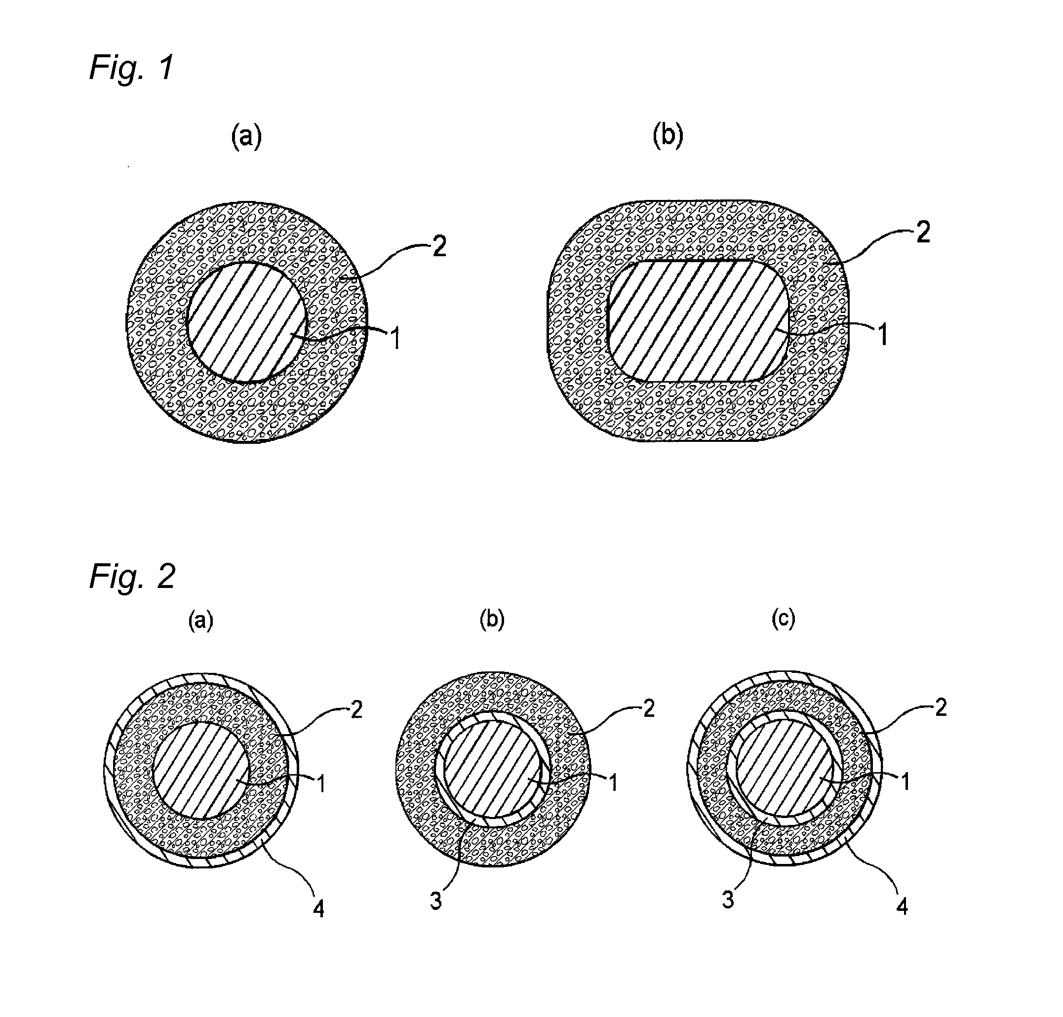
[0048]An extruded coating layer composed of the PEN resin with a thickness of 100 μm was formed on the periphery of a copper wire with a diameter of 1 mm, and the copper wire was put into a pressure container and subjected to a pressurization treatment at −25° C. and 1.7 MPa for 168 hours, thereby carbon dioxide gas was penetrated into the coating layer until saturation. Next, the copper wire was taken out from the pressure container and put into a hot air circulation-type foaming furnace that had been set to 100° C. for 1 minute to foam the coating layer, to give a foamed electrical wire of Example 1. A cross-sectional view of the obtained foamed electrical wire is shown in FIG. 2(a). With respect to the obtained foamed electrical wire of Example 1, measurements were conducted by the methods mentioned below. The results are shown in Table 1-1.

example 2

[0049]The foamed electrical wire of Example 2 was obtained in a similar manner to that in Example 1, except that the pressurization treatment was carried out in a carbon dioxide gas atmosphere at 0° C. and 3.6 MPa for 240 hours and a copper wire having an extruded coating layer was put into a hot air circulation-type foaming furnace that had been set to 120° C. A cross-sectional view of the obtained foamed electrical wire is shown in FIG. 2(a). With respect to the obtained foamed electrical wire of Example 2, similar measurements to those in Example 1 were conducted. The results are shown in Table 1-1.

example 3

[0050]The foamed electrical wire of Example 3 was obtained in a similar manner to that in Example 1, except that the pressurization treatment was carried out in a carbon dioxide gas atmosphere at −30° C. and 1.3 MPa for 456 hours and a copper wire having an extruded coating layer was put into a hot air circulation-type foaming furnace that had been set to 120° C. for 1 minute. A cross-sectional view of the obtained foamed electrical wire is shown in FIG. 2(a). With respect to the obtained foamed electrical wire of Example 3, similar measurements to those in Example 1 were conducted. The results are shown in Table 1-1.


PUM

PropertyMeasurementUnit
Temperatureaaaaaaaaaa
Lengthaaaaaaaaaa
Fractionaaaaaaaaaa

Abstract

A foamed electrical wire, containing: a conductor; and a foamed insulating layer; in which the foamed insulating layer comprises a thermoplastic resin that is a crystalline thermoplastic resin having a melting point of 150° C. or more or a non-crystalline thermoplastic resin having a glass transition temperature of 150° C. or more, and the average bubble diameter of the foamed insulating layer is 5 μm or less.

Description

TECHNICAL FIELD[0001]The present invention relates to a foamed electrical wire and a method of producing the same.BACKGROUND ART[0002]Inverters have been employed in many types of electrical equipments, as an efficient variable-speed control unit. Inverters are switched at a frequency of several kHz to tens of kHz, to cause a surge voltage at every pulse thereof. Inverter surge is a phenomenon in which reflection occurs at a breakpoint of impedance, for example, at a starting end, a termination end, or the like of a connected wire in the propagation system, followed by applying a voltage twice as high as the inverter output voltage at the maximum. In particular, an output pulse occurred due to a high-speed switching device, such as an IGBT, is high in steep voltage rise. Accordingly, even if a connection cable is short, the surge voltage is high, and voltage decay due to the connection cable is also low. As a result, a voltage almost twice as high as the inverter output voltage occu...

Claims


Application Information

Patent Timeline
IPC IPC(8): H01B3/30H01B13/06
CPCH01B3/301H01B3/306H01B7/0233H01B3/427H01B7/292H01B3/421H01B7/2813H01B7/02H01B13/14
Inventor MUTO, DAISUKEOYA, MAKOTOKOKUBO, YOUSUKETANAKA, AKIRA
Owner ESSEX FURUKAWA MAGNET WIRE LLC
Why Eureka
Try Eureka