Rotor refiner plate element for counter-rotating refiner having curved bars and serrated leading edges

a technology of counter-rotating and curved bars, which is applied in the field of disc refiners, can solve the problems of reducing the energy efficiency of the process, reducing affecting the quality of the finished product, so as to improve the overall refining efficiency, reduce the energy consumed to refine pulp, and prolong the operating life

Active Publication Date: 2013-01-17
ANDRITZ INC
View PDF7 Cites 23 Cited by
  • Summary
  • Abstract
  • Description
  • Claims
  • Application Information

AI Technical Summary

Benefits of technology

[0010]Designing the refiner plates to shift more of the energy input towards the periphery of the refining zone(s) should increase the overall refining efficiency and reduce the energy consumed to refine pulp. Shifting the energy input to the periphery of the refining zone(s), a larger operating gap between the refiner plates may be sufficient to provide a long operating life for the refiner plates.

Problems solved by technology

The compression and shear actions acting on the material separates of ligno-cellulosic fibers from the raw material, provides a certain amount of development or fibrillation of the material, and generates some fiber cutting which is usually less desirable.
In the mechanical pulping process, a large amount of friction occurs, such as between the wood chips and the refiner plates.
This friction reduces the energy efficiency of the process.
These techniques often result in reducing the thickness of the fibrous pad formed by the wood chips flowing between the refiner plates.
Reducing the gap may result in an increase in cutting of the fibers of the wood chips, a reduction of the strength properties of the pulp produced by the discs, an increased wear rate of the refiner plates and a reduction in the operating life of the refiner plates.
The shortness of the retention period in the peripheral region limits the amount of work that can be done in that most efficient part of the refining surface.

Method used


Image

  • Rotor refiner plate element for counter-rotating refiner having curved bars and serrated leading edges
  • Rotor refiner plate element for counter-rotating refiner having curved bars and serrated leading edges
  • Rotor refiner plate element for counter-rotating refiner having curved bars and serrated leading edges

Examples


Embodiment Construction

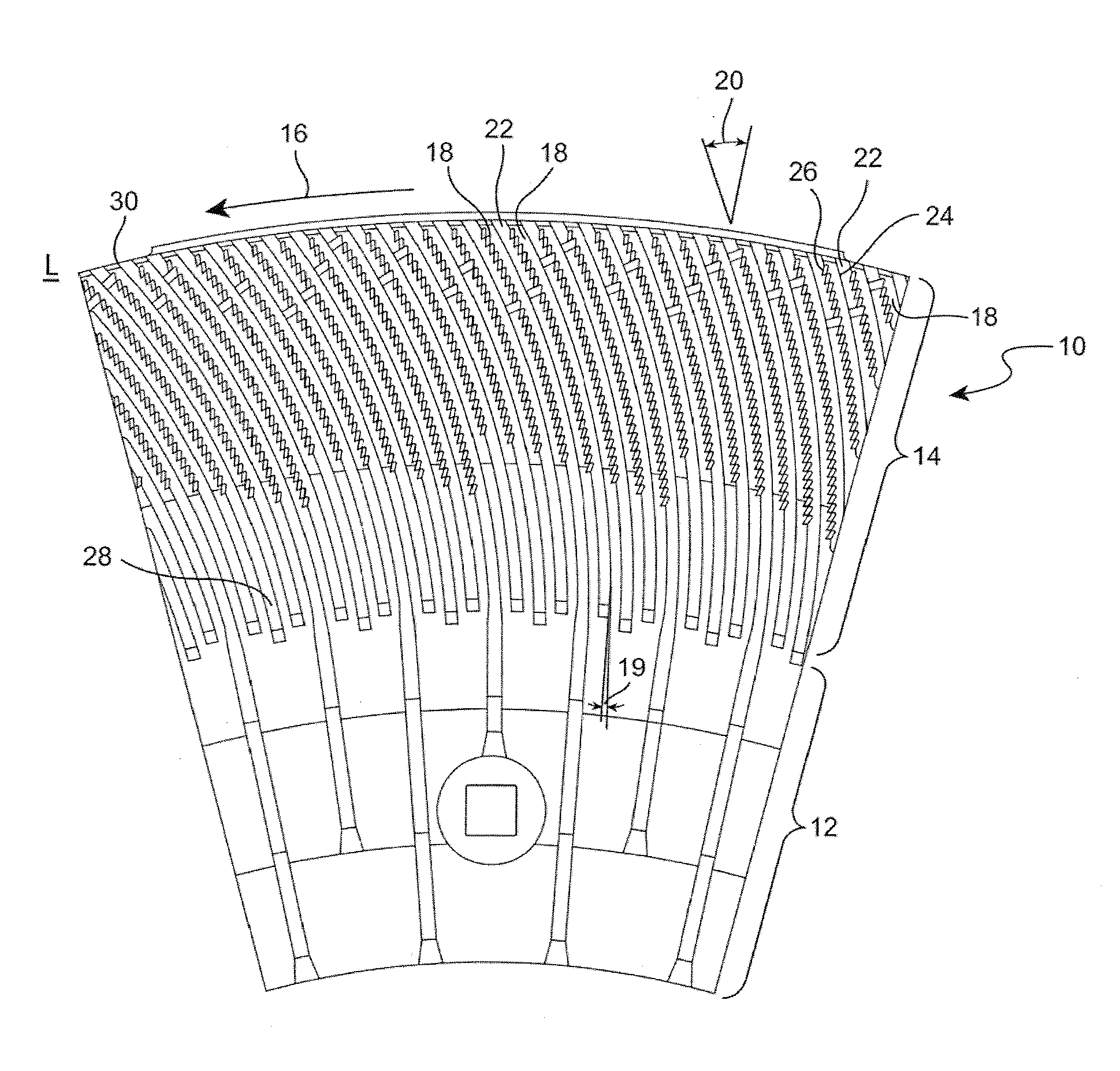
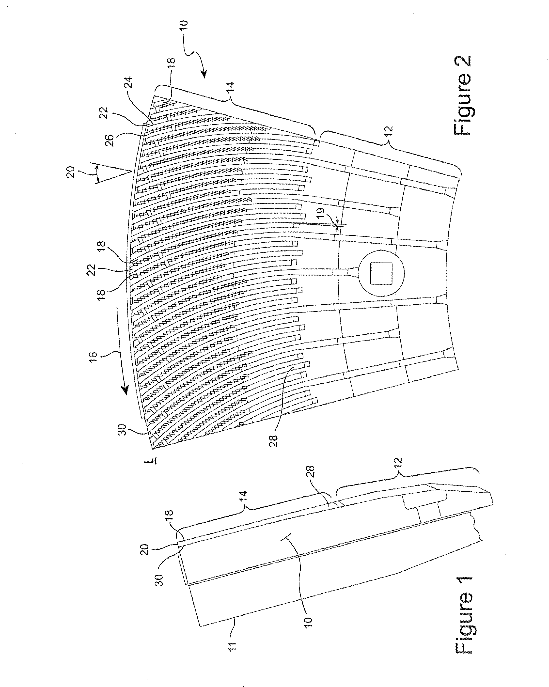
[0029]The refining process applies a cyclical compression to a fibrous pad formed of wood chips moving in the operating gap between discs of a mechanical refiner. The energy efficiency of the refining process may be improved by increasing the compression rate of the fibrous pad, and reducing the percentage of the refining energy applied at lower compression rates, such as at radially inward portions of the refining zone. The increased compression rate is achieved with the rotor plate designs disclosed herein without necessarily reducing the operating gap to the same extent done with conventional higher energy efficiency refiner plates.

[0030]A relatively wide operating gap between the rotor and stator plates in a refiner (as compared to the narrow gap in high energy efficiency refiners) results in a thicker pulp pad formed between the plates. A high compression ratio is achieved with a thick pulp pad using a significantly coarser refiner plate, as compared to conventional rotor plate...


PUM

PropertyMeasurementUnit
angleaaaaaaaaaa
angleaaaaaaaaaa
angleaaaaaaaaaa

Abstract

A refining plate segment for a mechanical refiner of lignocellulosic material including: a refining surface on a substrate, wherein the refining surface faces a refining surface of an opposing refiner plate, the refining surface including bars and grooves between the bars, wherein an angle of each bar with respect to a radial line corresponding to the bar increases at least 15 degrees along a radially outward direction, and the angle is a holdback angle in a range of 10 to 45 degrees at the periphery of the refining surface, and wherein the bars each include a leading sidewall having an irregular surface, wherein the irregular surface includes protrusions extending outwardly from the sidewall towards a sidewall on an adjacent bar and the irregular surface extends from at or near the outer periphery of the refining surface extends radially inwardly along the bars without reaching an inlet of the refining surface.

Description

RELATED APPLICATION[0001]This application claims the benefit of application Ser. No. 61 / 507,450 filed Jul. 13, 2011, which is incorporated in its entirety by reference.BACKGROUND OF THE INVENTION[0002]This invention relates to disc refiners for ligno-cellulosic materials, such as disc refiners used for producing mechanical pulp, thermomechanical pulp and a variety of chemi-thermomechanical pulps (collectively referred to as mechanical pulps and mechanical pulping processes).[0003]In counter-rotating refiners used in the mechanical pulping processes, raw material, typically wood or other ligno-cellulosic material (collectively referred to as wood chips), is fed through the middle of one of a refiners discs and propelled outwards by a strong centrifugal force created by the rotation of one or both rotor discs. Refiner plates are mounted on each of the opposing faces of the refiner discs. The wood chips move between the opposing refiner plates in a generally radially direction to the o...

Claims


Application Information

Patent Timeline
Patent Type & Authority Applications(United States)
IPC IPC(8): B02C7/12
CPCD21D1/306D21D1/303D21D1/30
Inventor GINGRAS, LUC
Owner ANDRITZ INC
Why Eureka
Try Eureka