Directional coupler and wireless communication device

Inactive Publication Date: 2013-01-31
TDK CORPARATION
View PDF6 Cites 19 Cited by
  • Summary
  • Abstract
  • Description
  • Claims
  • Application Information

AI Technical Summary

Benefits of technology

[0015]In another aspect, when a coupler can be shared in such a multi-band communication device (for example, a single coupler is provided), the number of parts can be reduced in the transmitter circuits to reduce the manufacturing cost of the device. Also, the portable communication device can be further redu

Problems solved by technology

However, in a semi-micro wave mainly used by mobile radio devices such as portable telephones, one quarter wavelength is very long, approximately 25 cm to 3 cm (for example, 3 cm for 10 GHz), so that it is not feasible from a viewpoint of the size to provide a coupling line of this length in a coupler for use in mobile radio devices such as portable telephones and the like which are required to be reduced in weight, thickness, length, and size.
Also, the use of a long coupling line equal to or larger than several centimeters would result in an extremely large insertion loss, which can cause a signification degradation of the battery life, which is a fatal disadvantage f

Method used


Image

  • Directional coupler and wireless communication device
  • Directional coupler and wireless communication device
  • Directional coupler and wireless communication device

Examples


second embodiment

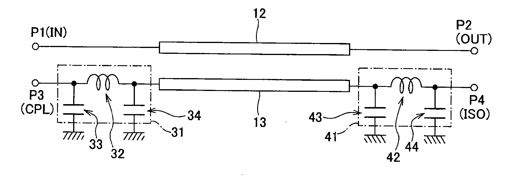
[0078]As shown in FIG. 5, a coupler according to a second embodiment of the present invention comprises an LPF unit (first LPF unit) 31 between a secondary line 13 and a coupling port P3, as is the case with the first embodiment, and additionally comprises an LPF unit (second LPF unit) 41 between the secondary line 14 and isolation port P4.

[0079]Notably, in this embodiment, each of the LPF units 31, 41 is a so-called n-type low pass filter which comprises two capacitors 33, 34; 43, 44 connected in parallel at both ends of the inductor 32, 42 which are connected in series. The first LPF unit 31 is made up of the inductor 32 inserted in series between the secondary line 13 and coupling port P3, and the capacitors 33, 34 connected at both ends of the inductor 32, respectively, between the transmission line and the ground which are located between the secondary line 13 and coupling port P3. The second LPF unit 41, in turn, is made up of the inductor 42 inserted in series between the sec...

third embodiment

[0081]As shown in FIG. 6, a coupler according to a third embodiment of the present invention comprises LPF units 51, 61 on both sides of a secondary line 13 (between a coupling port P3 and the secondary line 13 and between an isolation port P4 and the secondary line 13), respectively, as is the case with the coupler according to the second embodiment, and further in addition to these, comprises a capacitor 65 connected between the coupling port P3 and the isolation port P4. Here, each of the LPF units 51, 61 is an L-type low pass filter made up of an inductor 52, 62 and a capacitor 53, 63, similar to those of the first embodiment.

[0082]FIGS. 7 and 8 show the result of a simulation performed to reveal the frequency characteristic for the degree of coupling (FIG. 7) and isolation (FIG. 8) of the coupler according to the third embodiment, respectively, in comparison with those of a conventional coupler (which does not comprise the LPF units 51, 61 nor the capacitor 65 between P3 and P4...
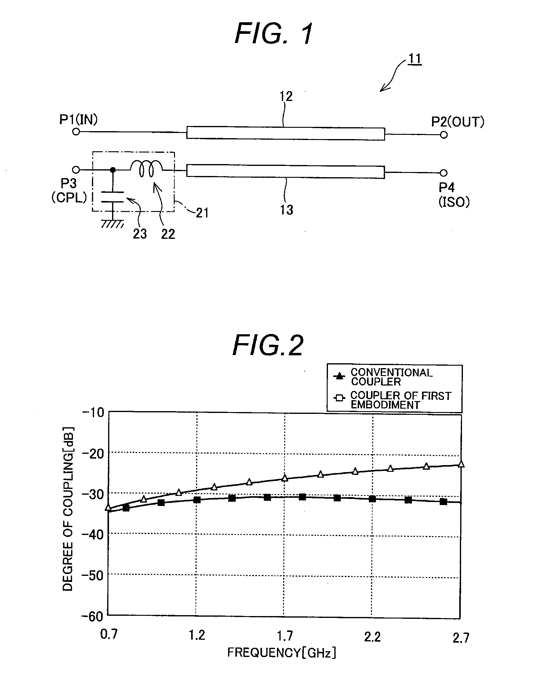
first embodiment

[Exemplary Modification to First Embodiment]

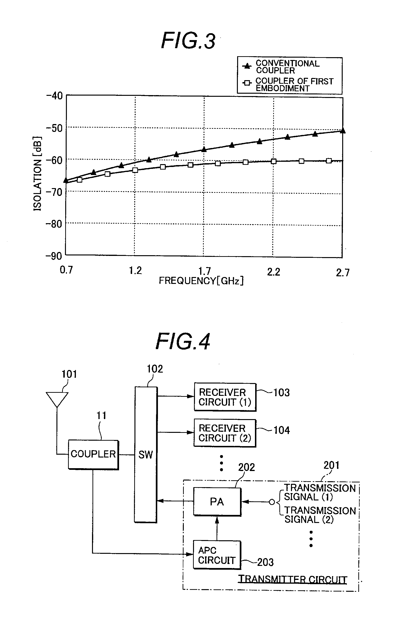
[0086]While the coupler 11 of the first embodiment can provide for a flat degree of coupling by adding the LPF unit 21, the LPF unit 21 connected in this way can sometimes cause a deterioration in isolation and directivity.

[0087]Specifically, the coupler establishes the directivity by a combination of an induced current and a displacement current on the secondary line. Therefore, a deterioration in isolation and directivity can often be caused by unwanted coupling between the coupling port and the output port, a phase shift of the induced current to the displacement current on the secondary line, and the like. In the first embodiment described above, on the other hand, the LPF unit 21 is connected to the secondary line 13. Presumably, the connection of the LPF unit 21 results in losing the balance of the phase difference between the induced current and displacement current on the secondary line 13, which can be a cause for giving rise to a...


PUM


Abstract

A directional coupler according to the present invention includes a primary line for transmitting a transmission signal; an input port for inputting the transmission signal to the primary line; an output port for outputting the transmission signal from the primary line; a secondary line for electromagnetically coupling with the primary line to extract part of the transmission signal; a coupling port provided at one end of the secondary line; an isolation port provided at the other end of the secondary line; and a low pass filter unit having a function of low pass filter, disposed between the secondary line and the coupling port.

Description

BACKGROUND OF THE INVENTION[0001]The present invention relates to a directional coupler and a wireless communication device, and more particularly, to techniques for providing a flat frequency characteristic for the degree of coupling in the directional coupler.[0002]A directional coupler (hereinafter simply referred to as the “coupler”), which enables extraction of part of power propagated on a transmission line, has become an indispensable component for designing a transmitter circuit of a variety of wireless communication devices such as portable telephones, wireless LAN communication device, communication devices of Bluetooth standard, and the like.[0003]Specifically, a coupler forms part of an adjuster means for controlling a transmission signal to maintain at a certain level. The adjuster means comprises a power amplifier (hereinafter referred to as the “PA”) capable of controlling a gain; a coupler for detecting the level of a transmission signal; and an automatic output cont...

Claims


Application Information

Patent Timeline
IPC IPC(8): H01P5/18H01Q1/50
CPCH01P5/18H03H7/0138H04B1/0053H04B1/0458
Inventor KUWAJIMA, HAJIMEFUJIWARA, TOSHIYASUOHYAMA, NAOTOTSUYA, YOSHIKAZUSASAKI, MASAMI
Owner TDK CORPARATION
Why Eureka
Try Eureka