Electrolytic capacitor and method of manufacturing the same

Active Publication Date: 2013-01-31
PANASONIC INTELLECTUAL PROPERTY MANAGEMENT CO LTD
View PDF4 Cites 27 Cited by
  • Summary
  • Abstract
  • Description
  • Claims
  • Application Information

AI Technical Summary

Problems solved by technology

The solid electrolytic capacitor is excellent particularly in the smaller ESR than the liquid electrolytic capacitor; however, its recovery action is poor at a failure of

Method used


Image

  • Electrolytic capacitor and method of manufacturing the same
  • Electrolytic capacitor and method of manufacturing the same
  • Electrolytic capacitor and method of manufacturing the same

Examples


Embodiment Construction

[0019]Prior to the description of the exemplary embodiment of the present invention, a method of manufacturing a conventional hybrid electrolytic capacitor shown in FIG. 4 is described hereinafter.

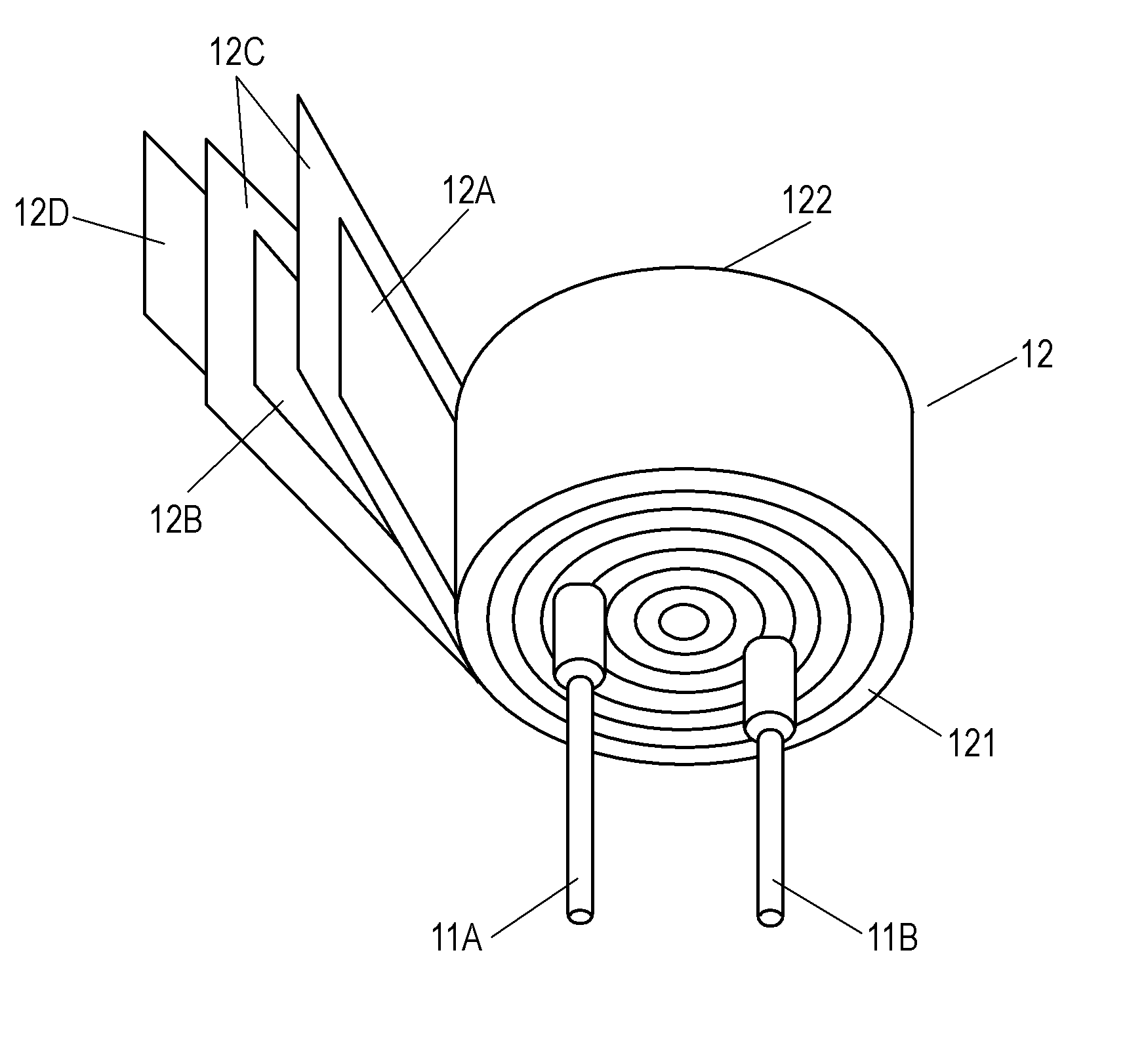
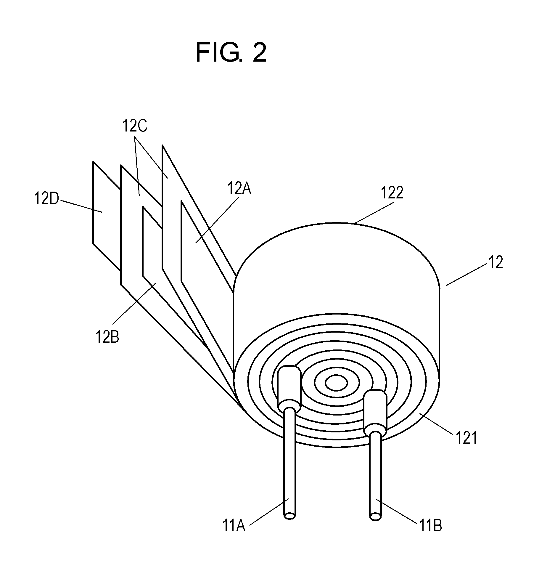
[0020]First, as shown in FIG. 5, prepare anode foil 2A, cathode foil 2B, and separator 2C. Anode foil 2A is formed of valve metal, e.g. aluminum, and includes dielectric layer 2E made of anodic oxide film on its surface. Then connect first ends of lead wire 1A, 1B to anode foil 2A, cathode foil 2B respectively. Next, interpose separator 2C between anode foil 2A and cathode foil 2B, and roll them together into a cylindrical shape. Then fasten the cylindrical shape with insulating tape 2D on the outer wall to form capacitor element 2.

[0021]Next, form conductive polymer layer 6 between anode foil 2A and cathode foil 2B of capacitor element 2. Conductive polymer layer 6 is formed this way: First, disperse fine particles of polyethylene dioxythiophene containing dopant agent into solvent, i.e. ...


PUM

PropertyMeasurementUnit
Lengthaaaaaaaaaa
Lengthaaaaaaaaaa
Nanoscale particle sizeaaaaaaaaaa

Abstract

An electrolytic capacitor includes a capacitor element and an electrolyte solution impregnated into the capacitor element. The capacitor element includes an anode foil, cathode foil, separator, and a solid electrolytic layer. The anode foil has a dielectric layer on its surface, and the cathode foil confronts the anode foil. The separator is interposed between the anode foil and the cathode foil. The solid electrolytic layer is formed on the surfaces of the anode foil, cathode foil, and separator as an aggregate of fine particles of conductive polymer. The separator has an air-tightness not greater than 2.0 s/100 ml. Sizes of the fine particles measure not greater than 100 nm in diameter, and the fine particles are contained in an amount ranging from 0.3 mg/cm2 to 1.2 mg/cm2 converted to amounts per unit area of the anode foil.

Description

BACKGROUND[0001]1. Field[0002]The present invention relates to electrolytic capacitors to be used in a variety of electronic devices, electric devices, industrial devices, and automotive devices. It also relates to a method of manufacturing the same capacitors.[0003]2. Background Art[0004]The electronic devices have adopted digital technology, so that the capacitors employed in output side circuits, e.g. a smoothing circuit or a control circuit, of the power supplies of those devices need to be smaller in size and greater in capacity. On top of that, the capacitor is desired to have a smaller equivalent series resistance (hereinafter simply referred to as ESR) in a high frequency band. A liquid impregnated capacitor that employs liquid electrolyte such as electrolyte solution has been typically used in the output side circuit of the power supply. However, in recent years, solid electrolytic capacitors have been used for the same purpose, and they employ solid electrolyte such as tra...

Claims


Application Information

Patent Timeline
IPC IPC(8): H01G9/048
CPCH01G11/52Y02E60/13H01G9/042H01G9/0029H01G11/56H01G9/025H01G9/02H01G11/28Y10T29/417H01G9/145H01G13/02
Inventor AOYAMA, TATSUJIMATSUURA, HIROYUKIMURATA, YUUKISHIMOYAMA, YUKIYAKUSHIZAKI, JYUNYASASAKI, HIDEHIRO
Owner PANASONIC INTELLECTUAL PROPERTY MANAGEMENT CO LTD
Why Eureka
Try Eureka