Method and apparatus for transmitting sparse signal, and method and apparatus for recovering sparse signal via belief propagation and bayesian hypothesis test

a technology of belief propagation and bayesian hypothesis, applied in the direction of pulse technique, instruments, code conversion, etc., can solve the problems of low signal recovery success rate and exponential increase in complexity, and achieve high signal recovery success rate, low complexity, and rapid scan of target signals

Inactive Publication Date: 2013-02-07
GWANGJU INST OF SCI & TECH
View PDF0 Cites 15 Cited by
  • Summary
  • Abstract
  • Description
  • Claims
  • Application Information

AI Technical Summary

Benefits of technology

[0009]Another objective of the present invention is to provide an apparatus and a method for recovering a sparse signal via a belief propagation and a Bayesian hypothesis test (BHT). In other words, the objective of the present invention is to provide an apparatus and a method for recovering a sparse signal, in which the recovering of the sparse signal is defined in terms of probability through a maximum a posterior (MAP) scheme, and the MAP scheme is performed by combination of a support set detection part and a signal value estimation part, so that the signal can be recovered.
[0044]As described above, according to the embodiment of the present invention, since the sparse signal transmitting device compresses the target signal based on a sparse binary matrix, the sparse signal transmitting device can be readily realized in hardware, and can rapidly scan the target signal while compressing the target signal. In addition, according to the embodiment of the present invention, the sparse signal recovering device can recover a signal with the maximum probability according to a given measurement matrix and the sparsity of the target signal. The minimum length of the measurement signal required when the signal is recovered is slowly increased, so that low complexity is represented. In addition, the sparse signal recovering device represents a high signal recovery success rate, and can effectively remove a noise component added to a signal component by using the prior information about the target signal and the statistical information about the noise component.

Problems solved by technology

However, according to the method for recovering the sparse signal, since xCK search operations are required in order to recover the target signal x, complexity is exponentially increased if the values of N and K are increased.
However, the above schemes represent a low recovery success rate, or are applicable to very sparse signals.

Method used


Image

  • Method and apparatus for transmitting sparse signal, and method and apparatus for recovering sparse signal via belief propagation and bayesian hypothesis test
  • Method and apparatus for transmitting sparse signal, and method and apparatus for recovering sparse signal via belief propagation and bayesian hypothesis test
  • Method and apparatus for transmitting sparse signal, and method and apparatus for recovering sparse signal via belief propagation and bayesian hypothesis test

Examples


first embodiment

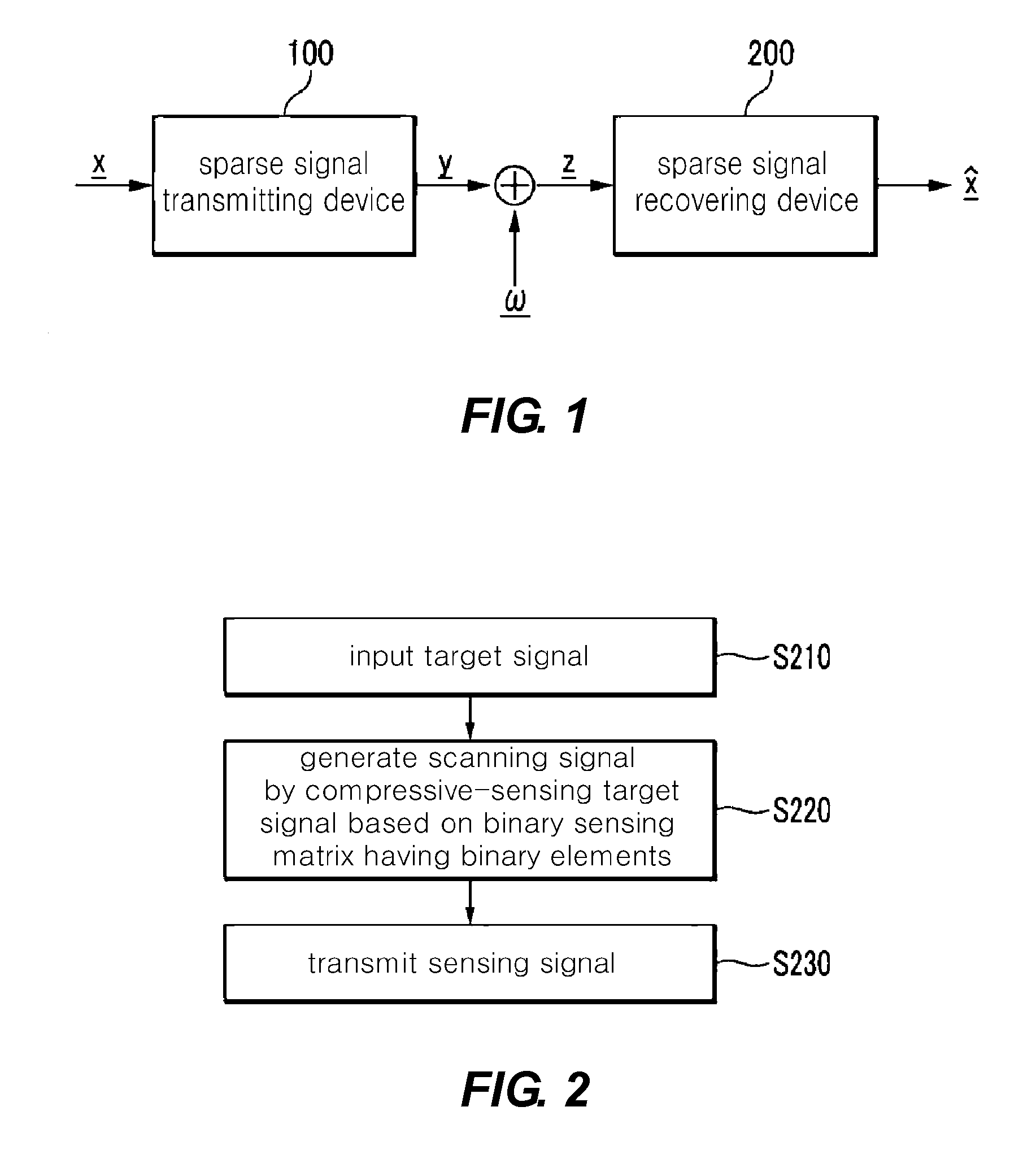
[0062]FIG. 1 is a sectional view schematically showing a compressive sensing system according to the present invention.

[0063]Referring to FIG. 1, the compressive sensing system includes a sparse signal transmitting device 100 and a sparse signal recovering device 200.

[0064]The sparse signal transmitting device 100 generates a measurement signal y by sensing a target signal x based on a sensing matrix Φ having a sparse characteristic. The target signal x is a sparse signal, and elements of the target signal x have non-zero values with predetermined probability q. In this case, the sensing matrix Φ is an M×N sensing matrix representing a sparse characteristic. Each element φji of the sensing matrix Φ has a value of “0” or “1”. The φji represents a (j,i)th element of the sensing matrix Φ.

[0065]The sparse signal transmitting device 100 senses the target signal x by projecting the target signal x to the sensing matrix Φε{0,1}M×N. Since the sensing matrix Φ is an M×N matrix having the num...

second embodiment

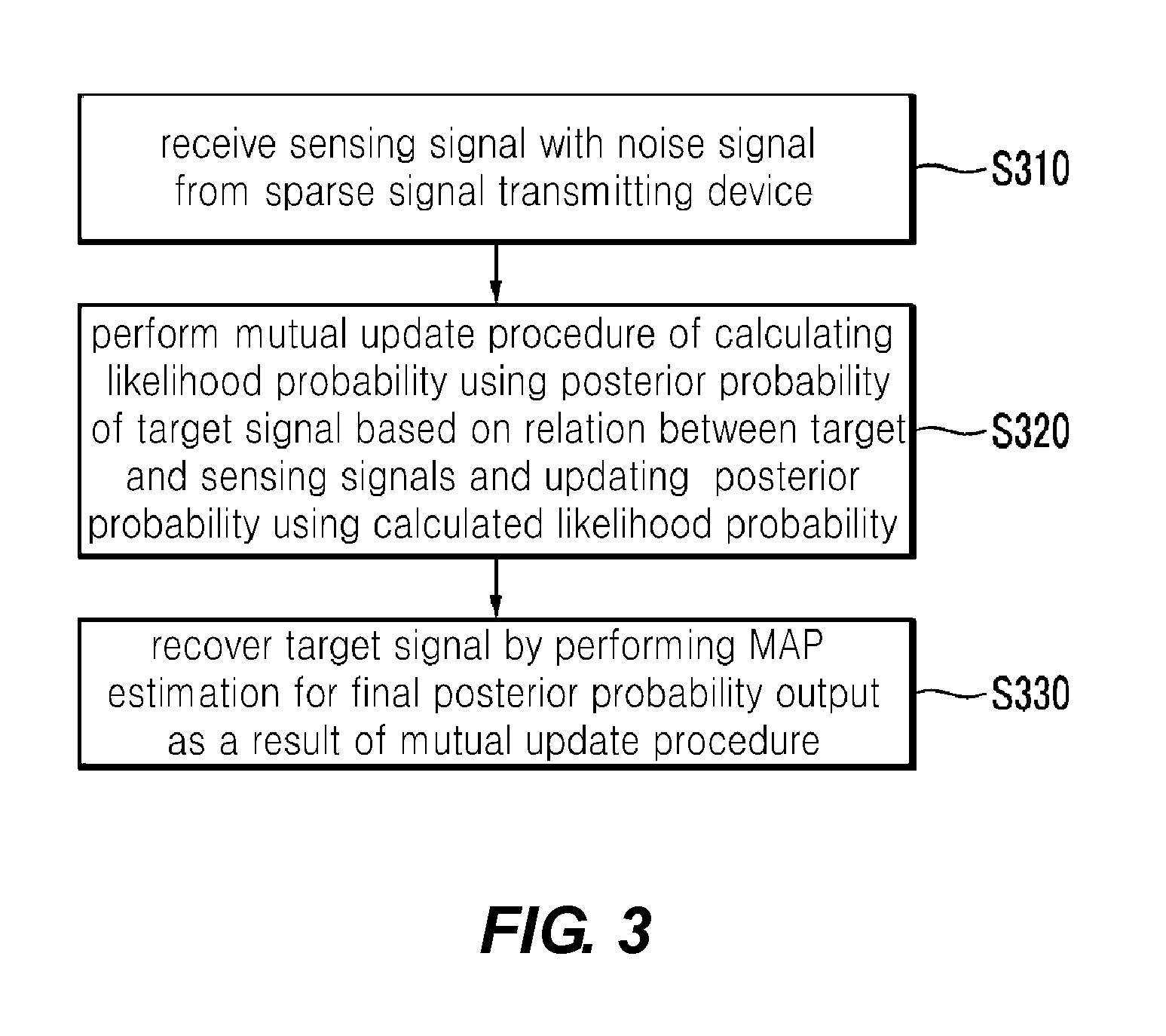
[0084]FIG. 4 is a flowchart showing the method for recovering the sparse signal according to the present invention. Referring to FIG. 4, the sparse signal recovering device 200 updates probability information mi→jl of a target signal element and probability information mj→il of a measurement signal element, which are related to the target signal element, by exchanging the probability information mi→jl of the target signal element and the probability information mj→il of the measurement signal element by the predetermined number of times. The sparse signal recovering device 200 recovers the target signal by performing the MAP estimation based on the updated probability information.

[0085]The sparse signal recovering device 200 initializes the probability information of the measurement signal element z, transferred to the target signal element xi (step S410). In other words, the sparse signal recovering device 200 can initialize the probability information of the measurement signal ele...

third embodiment

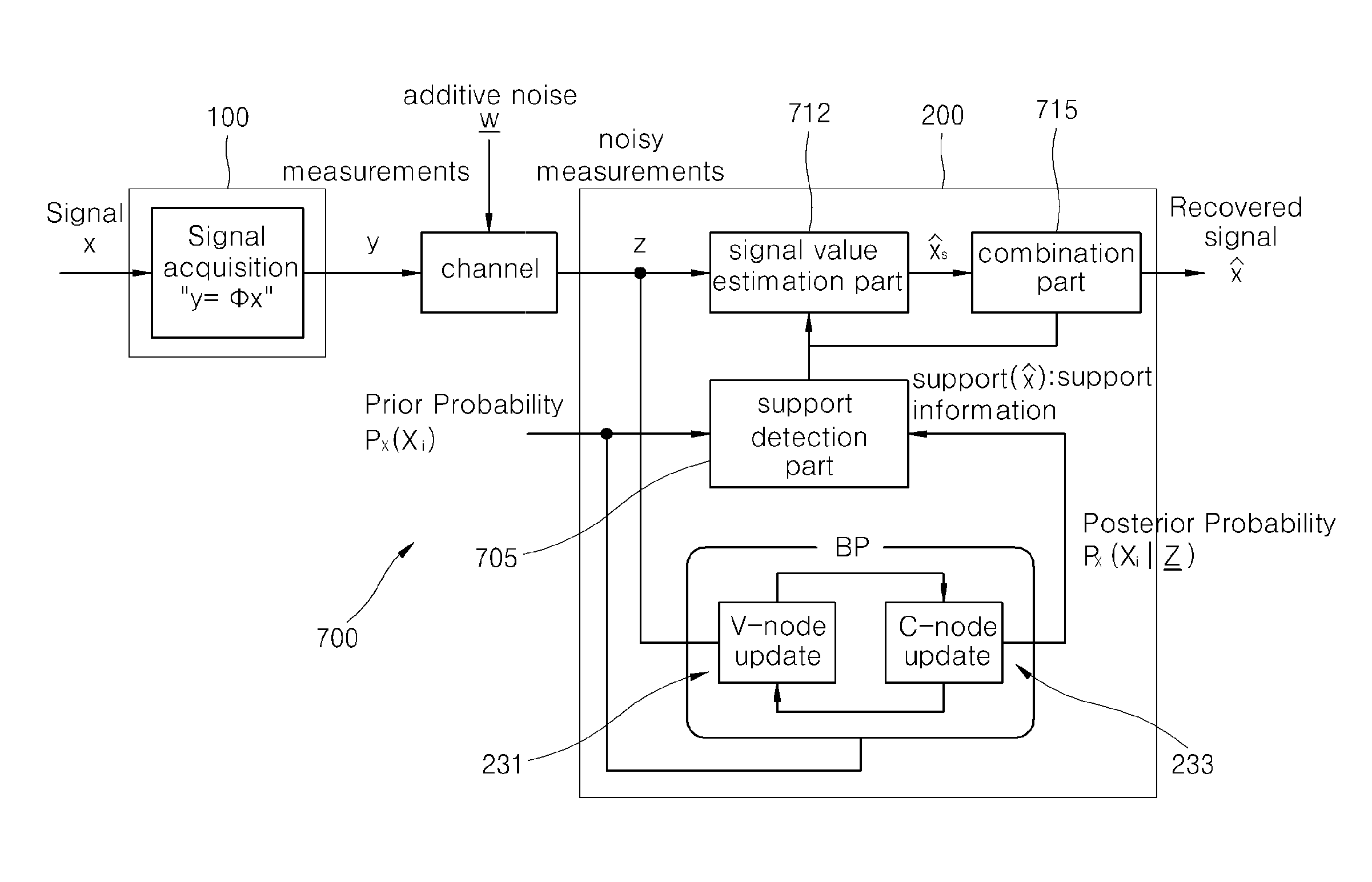
[0107]Hereinafter, the present invention will be described in detail with reference to FIGS. 7 to 14.

[0108]FIG. 7 shows a block diagram showing a sparse signal recovering device 700 according to the third embodiment of the present invention. Referring to FIG. 7, when comparing the structure of FIG. 6, a support detection part 705 serving as a Bayesian hypothesis test part, a signal value estimation part 712 serving as a minimum mean square error estimator (MMSE), and a combining part 715 are further included.

[0109]Through a sparse signal recovering algorithm applied to the sparse signal recovering device 700 according to the third embodiment of the present invention having the structure of FIG. 7, the recovering scheme of a target signal is defined through the MAP (Maximum a posterior) scheme in terms of probability, and the MAP scheme is performed by combination of the a signal support set detection part and a signal value estimation part, so that the signal can be recovered. In th...


PUM


Abstract

Disclosed are a method and an apparatus for transmitting a sparse signal, and a method and an apparatus for recovering the sparse signal. The method for recovering a sparse signal by using a sparse signal recovering device that recovers a target signal from a received signal includes receiving a measurement signal with a noise signal from a sparse signal transmitting device which scans a target signal based on a measurement matrix, performing a mutual update procedure in which a likelihood probability is calculated by using a posterior probability of the target signal based on a relation between the target signal and the measurement signal, and the posterior probability is updated by using the likelihood probability, and recovering the target signal by performing maximum a posterior estimation for a final posterior probability output through the mutual update procedure.

Description

CROSS-REFERENCE TO RELATED APPLICATION[0001]This application claims the benefit under 35 U.S.C. §119 of Korean Patent Application No. 10-2011-0077836 filed on Aug. 4, 2011 in the Korean Intellectual Property Office, the entirety of which disclosure is incorporated herein by reference.BACKGROUND OF THE INVENTION[0002]1. Field of the Invention[0003]The present invention relates to a method and an apparatus for transmitting a sparse signal, and a method and an apparatus for recovering the sparse signal via a belief propagation and a Bayesian hypothesis test (BHT).[0004]2. Description of the Related Art[0005]When a signal length of a sparse signal is N, the sparse signal includes K (N>>K) non-zero elements and (N−K) zero elements. A compressed sensing scheme is a signal compressing and processing scheme capable of significantly reducing an amount of information of the sparse signal.[0006]A transmitter generates a measurement signal y obtained by compressing and sensing a target sp...

Claims


Application Information

Patent Timeline
Patent Type & Authority Applications(United States)
IPC IPC(8): G06N5/00H04B1/66
CPCH04B1/66H03M7/30G06N5/00
Inventor LEE, HEUNG-NOKIM, KISEONKANG, JAEWOOK
Owner GWANGJU INST OF SCI & TECH
Why Eureka
Try Eureka