Sequentially laminated, rare earth, permanent magnets with dielectric layers reinforced by transition and/or diffusion reaction layers

Inactive Publication Date: 2013-02-14
ELECTRON ENERGY CORP
View PDF0 Cites 13 Cited by
  • Summary
  • Abstract
  • Description
  • Claims
  • Application Information

AI Technical Summary

Benefits of technology

[0021]A primary object of the invention is to produce mechanically strong, high electrical resistivity, Sm—Co and Nd—Fe—B, sequentially laminated, rare earth, permanent magnets with dielectric layers separate

Problems solved by technology

Eddy currents result in building up heat which adversel

Method used


Image

  • Sequentially laminated, rare earth, permanent magnets with dielectric layers reinforced by transition and/or diffusion reaction layers
  • Sequentially laminated, rare earth, permanent magnets with dielectric layers reinforced by transition and/or diffusion reaction layers
  • Sequentially laminated, rare earth, permanent magnets with dielectric layers reinforced by transition and/or diffusion reaction layers

Examples


example 1

FIGS. 1 and 2

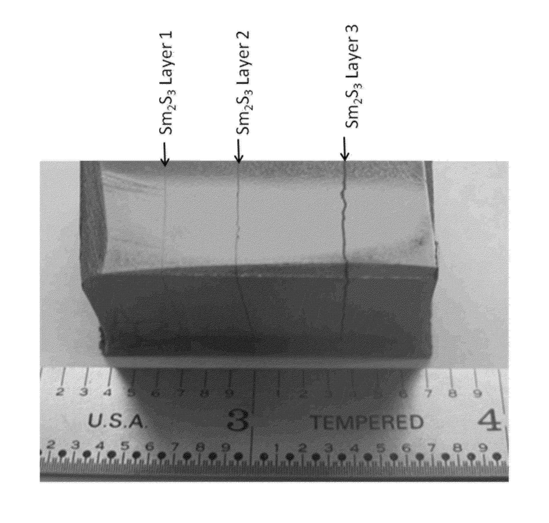
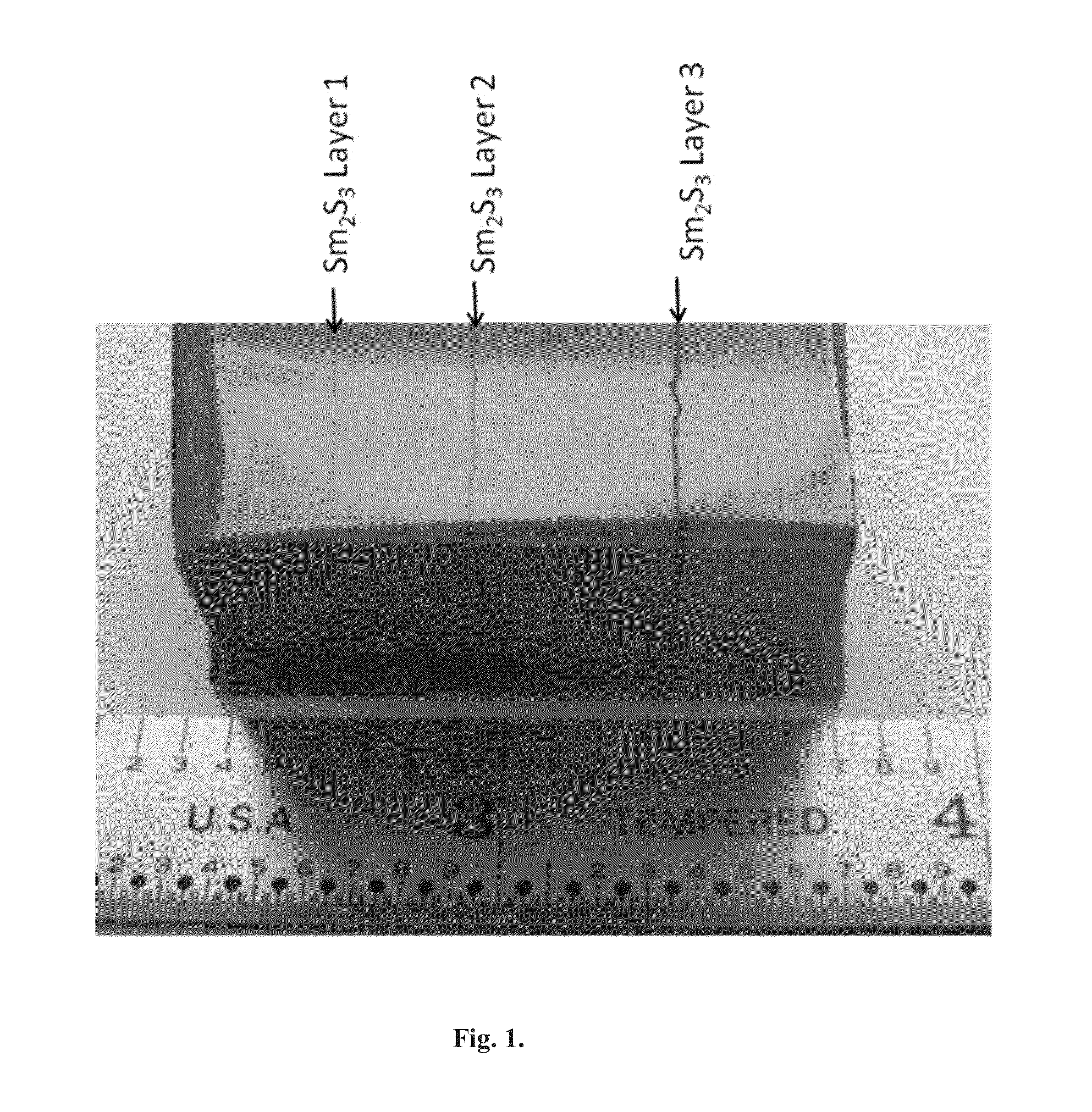
[0155]An anisotropic Sm(Co,Fe, Cu,Zr)z / Sm2S3 sequentially laminated magnet with increased electrical resistivity was synthesized by regular powder metallurgic processes consisting of sintering at from 1200° C. to 1220° C., solution treatment at from 1160° C. to 1180° C. and aging at from 830° C. to 890° C. This step was followed by a slow cooling to 400° C. The sequentially laminated, anisotropic magnet consisting of three sequential Sm(Co,Fe, Cu,Zr)z layers and three sequential Sm2S3 layers surrounded by diffusion reaction layers of the present invention, shown in FIG. 1, was produced by a one-step sintering process.

[0156]The photograph set out in FIG. 2 shows the thickness and uniformity of the sulfide-based, dielectric layer of a sequentially laminated anisotropic magnet. In the process of the present invention, this thickness and uniformity of sulfide-based, dielectric layers and the associated transition and / or diffusion reaction layers is controlled by spraying a ...

example 2

FIGS. 3 and 4

[0157]FIG. 3 shows an optical micrograph of a Sm2S3 colloidal layer deposited on a Sm(Co,Fe, Cu,Zr)z sequentially laminated magnet after polishing and etching. The Sm2S3 dielectric layer is about 190 μm thick. The magnetic layers and interface diffusion reaction layers of the present invention separating the sulfide-based, dielectric layer from the permanent magnet layers are clearly shown. The demagnetization curve for this sequentially laminated, permanent magnet of the invention compared to conventional non-layered magnets indicates comparable magnetic properties. The magnetic properties of the sequentially laminated Sm(Co,Fe, Cu,Zr)z / Sm2S3 magnet shown in FIG. 3 were reported in FIG. 4, as follows:

[0158]Residual induction: Br=10.516 kG

[0159]Intrinsic coercivity: Hci>24.5 kOe

[0160]Maximum energy product: (BH)max=25.5 MGOe

[0161]The electrical resistivity of this sequentially laminated, rare earth, permanent magnet of the invention was unexpectedly increased by approxi...

example 3

FIG. 5

[0162]FIG. 5 shows an optical micrograph of a Sm2S3 colloidal, dielectric layer deposited on a Sm(Co,Fe, Cu,Zr)z sequentially laminated magnet after polishing and etching. The Sm2S3 dielectric layer is about 30 μm thick. The magnetic layers and interface diffusion reaction layers of the present invention separating the sulfide-based, dielectric layer from the permanent magnet layers are clearly shown. The demagnetization curve for this sequentially laminated, permanent magnet of the invention compared to conventional non-layered magnets indicates comparable magnetic properties. The magnetic properties of the laminated Sm(Co,Fe, Cu,Zr)z / Sm2S3 magnet shown in FIG. 5 were as follows:

[0163]Residual induction: Br=10.73 kG

[0164]Intrinsic coercivity: Hci>24.5 kOe

[0165]Maximum energy product: (BH)max=25.5 MGOe

[0166]The electrical resistivity of this sequentially laminated, permanent magnet of the invention was unexpectedly increased by approximately 35 times (about 3000%) compared to ...


PUM


Abstract

Laminated, rare earth, permanent magnets with one or more dielectric layers, suitable for use in high performance, rotating machines comprising: sequential laminates of permanent magnet layers and dielectric layers separated by transition and/or diffusion reaction layers, where said sequentially laminated magnets indicate increased electrical resistivity with improved mechanical strength.

Description

FIELD OF THE INVENTION[0001]The present invention is directed to mechanically strong, sequentially laminated, rare earth, permanent magnets having dielectric layers separated from permanent magnet layers by transition and / or diffusion reaction layers, where the transition and / or diffusion reaction layers impart an unexpected improvement in mechanical strength to the sequentially laminated, rare earth, permanent magnets.BACKGROUND OF THE INVENTION[0002]The present invention relates to sequentially laminated, rare earth, permanent magnets for use in high performance, rotating machines featuring dielectric layers reinforcing transition and / or diffusion reaction layers. The high electrical resistivity, rare earth, permanent magnets of the invention, with reinforced dielectric layers; are characterized by reduced eddy current losses combined with improved mechanical strength suitable for use in high performance, rotating machines. Rare earth, permanent magnets of the invention featuring ...

Claims


Application Information

Patent Timeline
IPC IPC(8): H02K21/12H01F7/02
CPCH01F7/021H02K1/02H01F10/126H01F1/057H01F1/055
Inventor LIU, JINFANGCHINNASAMY, CHINSBENDER, JOSHUA L.MARINESCU, MELANIA
Owner ELECTRON ENERGY CORP
Why Eureka
Try Eureka