Thermal Management System and Method

a management system and thermal management technology, applied in the direction of printed circuit aspects, electrical apparatus construction details, stacked spaced pcbs, etc., can solve the problems of increasing adding to the overall cost of the wave soldering process, and not eliminating options, so as to enhance the conductivity path, maintain the thermal safety margin of components, and enhance the conductivity

Active Publication Date: 2013-02-28
TDK LAMBDA CORP
View PDF21 Cites 33 Cited by
  • Summary
  • Abstract
  • Description
  • Claims
  • Application Information

AI Technical Summary

Benefits of technology

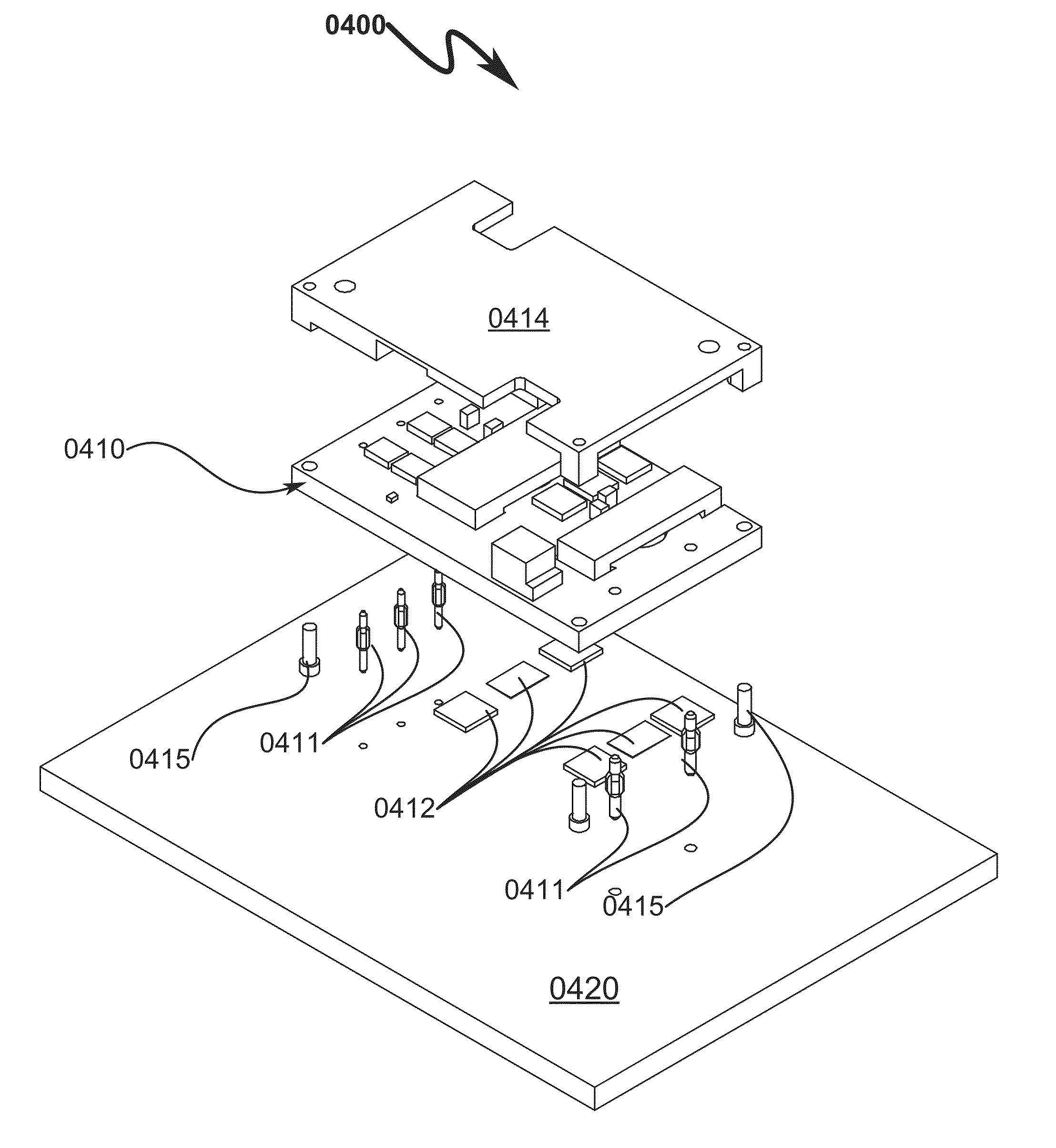
[0037]Controlled electrical isolation between the two PCBs is provided for using spacer pads that may also be thermal conductive. Contact paste incorporated in some embodiments permits enhanced conductivity paths between the heat sourcing PCB, a thermally conductive plate mounted over the heat sourcing PCB, and the heat sinking PCB. The use of self-centering support pins incorporating out-gassing vents in some embodiments allows reflow/wave/hand soldering as desired.
[0038]The system/method as disclosed is suitable for any combination of reflow/wave/hand soldering and thus permits conventional DC-DC power conversion modul

Problems solved by technology

Hand soldering of through-hole power modules is a slow, manual-intensive process, and requires that both the customer's main printed circuit board (PCB) and the DC-DC converter module be pre-heated in order to solder the through-hole pins to the customer's PCB.
Additionally, there is also a significant amount of hazardous material treatment associated with wave soldering which also adds to the overall expense of the wave soldering process.
However, this option does not eliminate problems associated with assembling DC-DC modules with attached thermal base plates.
This option also drives the cost of DC-DC power modules and the customer's PCB higher, since more expensive PWB fabrication techniques must be employed to deliver the electrical current from the top mounting layer of the customer PCB to the sub-surface thermally conducting layers of the PWBs.
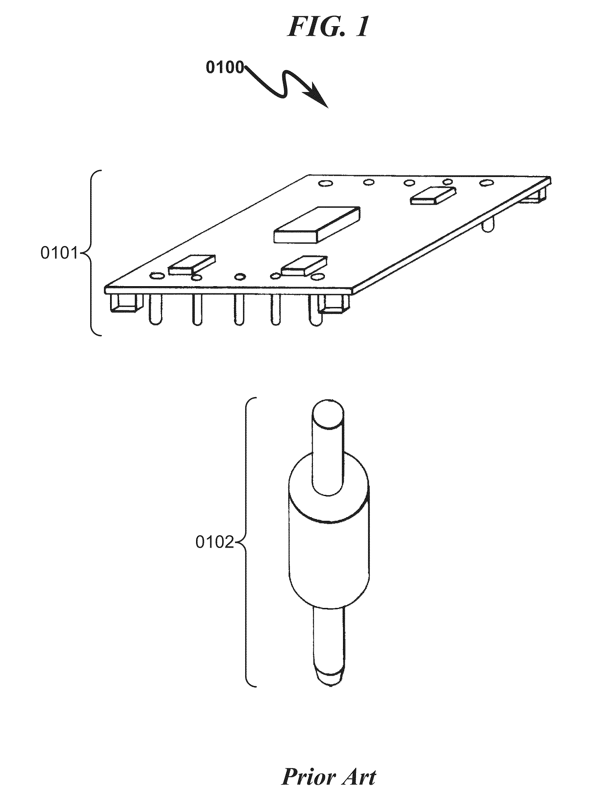
Unfortunately, our present through-hole DC-DC power module designs that incorporate heat spreader plates (known generally as “base plates”) cannot be reflow assembled.
The prior art fails to describe any techniques and materials that can be used to fabricate base-plated power modules that can be reflow assembled, while, at the same time, providing other desirable features for the final assembly of modules with the customer's main PCB board.
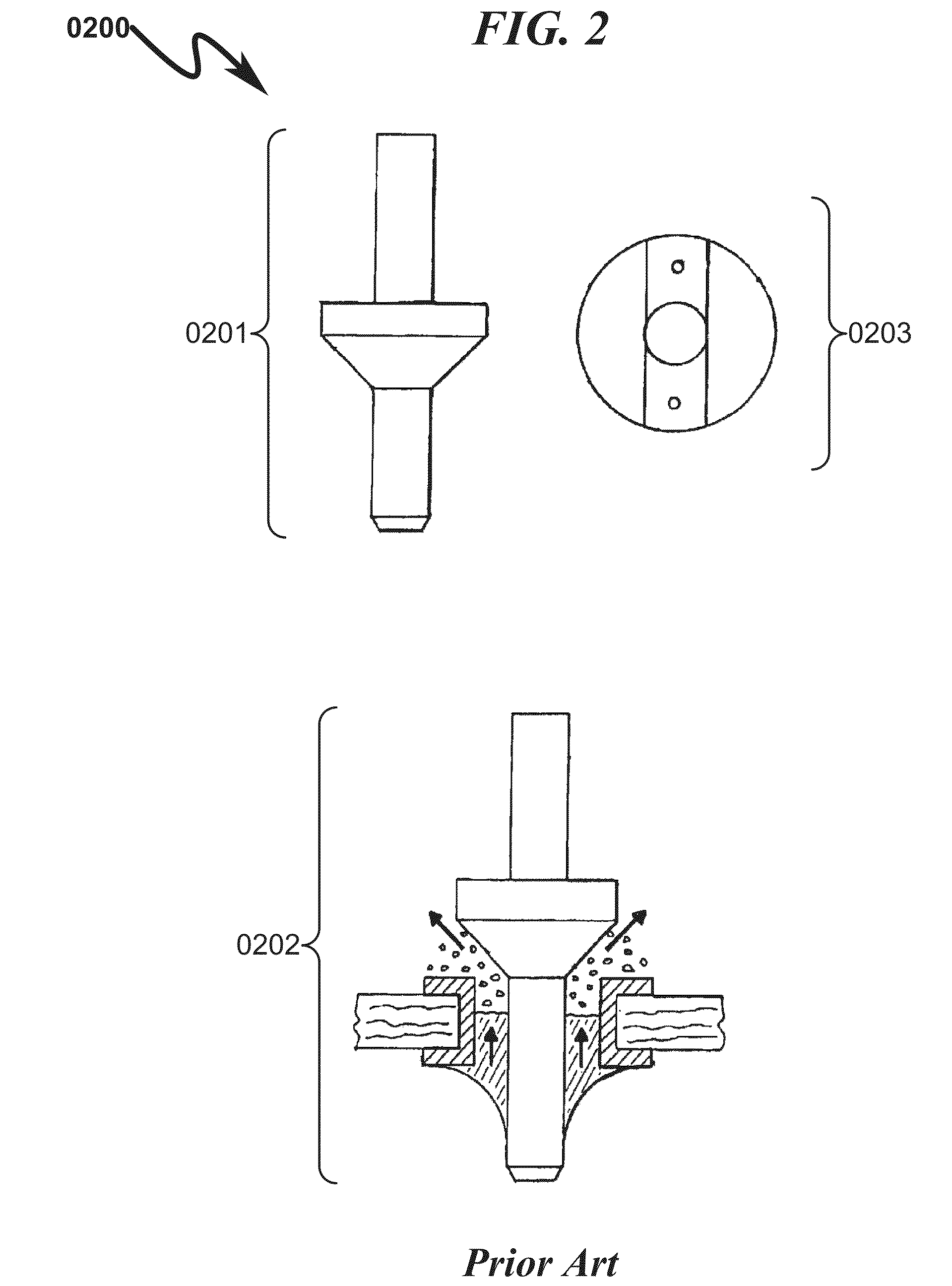
While this patent makes use of reflow soldering process technology, the wicking features of the flange pin described may not be sufficient to prevent voids and other structural anomalies from degrading the electrical/thermal characteristics of the flange/PCB junction.
The prior art as detailed above suffers from the following deficiencies:Insufficient Heat Dissipation Capability.
In many challenging high density power conversion systems, the heat dissipation capability of the power conversion module when used in conjunction with heat conducting support pins and/or a top heat sink plate is insufficient.
Furthermore, the prior art does not teach any methodology to improve the heat conduction from the heat source PCB to a connected heat sink PCB.Thermal Transfer Compound Expansion.
Once the so

Method used


Image

  • Thermal Management System and Method
  • Thermal Management System and Method
  • Thermal Management System and Method

Examples


Embodiment Construction

[0080]While this invention is susceptible of embodiment in many different forms, there is shown in the drawings and will herein be described in detailed preferred embodiment of the invention with the understanding that the present disclosure is to be considered as an exemplification of the principles of the invention and is not intended to limit the broad aspect of the invention to the embodiment illustrated.

[0081]The numerous innovative teachings of the present application will be described with particular reference to the presently preferred embodiment, wherein these innovative teachings are advantageously applied to the particular problems of a THERMAL MANAGEMENT SYSTEM AND METHOD. However, it should be understood that this embodiment is only one example of the many advantageous uses of the innovative teachings herein. In general, statements made in the specification of the present application do not necessarily limit any of the various claimed inventions. Moreover, some statemen...


PUM

PropertyMeasurementUnit
Angleaaaaaaaaaa
Angleaaaaaaaaaa
Pressureaaaaaaaaaa

Abstract

A thermal management system/method allowing efficient electrical/thermal attachment of heat sourcing PCBs to heat sinking PCBs using reflow/wave/hand soldering is disclosed. The disclosed system/method may incorporate a combination of support pins, spacer pads, and/or contact paste that mechanically attaches a heat sourcing PCB (and its associated components) to a heat sinking PCB such that thermal conductivity between the two PCBs can be optimized while simultaneously allowing controlled electrical conductivity between the two PCBs. Controlled electrical isolation between the two PCBs is provided for using spacer pads that may also be thermal conductive. Contact paste incorporated in some embodiments permits enhanced conductivity paths between the heat sourcing PCB, a thermally conductive plate mounted over the heat sourcing PCB, and the heat sinking PCB. The use of self-centering support pins incorporating out-gassing vents in some embodiments allows reflow/wave/hand soldering as desired.

Description

CROSS REFERENCE TO RELATED APPLICATIONS[0001]This patent application is a continuation-in-part (CIP) of parent U.S. Utility patent application for “IC THERMAL MANAGEMENT SYSTEM”, Ser. No. 12 / 912,476, docket AINNO.0126, filed electronically with the USPTO on Oct. 26, 2010 with EFS ID 8707113 and Confirmation Number 2130.[0002]Applicants claim benefit pursuant to 35 U.S.C. §120 and hereby incorporates by reference U.S. Utility patent application for “IC THERMAL MANAGEMENT SYSTEM”, Ser. No. 12 / 912,476, docket AINNO.0126, filed electronically with the USPTO on Oct. 26, 2010 with EFS ID 8707113 and Confirmation Number 2130.[0003]Applicants claim benefit pursuant to 35 U.S.C. §119 and hereby incorporates by reference U.S. Provisional Patent Application for “THERMAL MANAGEMENT SYSTEM AND METHOD”, Ser. No. 61 / 664,940, docket AINNO.0128P, filed electronically with the USPTO on Jun. 27, 2012 with EFS ID 13119127 and Confirmation Number 4912.PARTIAL WAIVER OF COPYRIGHT[0004]All of the material...

Claims


Application Information

Patent Timeline
IPC IPC(8): H05K7/20H05K3/34
CPCH05K2201/10409H05K2201/1056H05K2201/10871H05K1/0203H05K1/0204Y10T29/49144H05K2201/042H05K2201/10303H05K7/20454H05K7/205H05K1/144H05K7/20463
Inventor ALBRECHT, III, L. RAYLEE, GORDON K.Y.HE, JIN
Owner TDK LAMBDA CORP
Why Eureka
Try Eureka