Fabrication method of cylindrical gratings

a technology of cylindrical gratings and fabrication methods, which is applied in the field of fabrication methods of cylindrical gratings, can solve the problems of improper approach to use only a very small fraction of the available power of light sources, and inability to achieve fine pitch cylindrical gratings

Active Publication Date: 2013-02-28
SICK AG
View PDF2 Cites 14 Cited by
  • Summary
  • Abstract
  • Description
  • Claims
  • Application Information

AI Technical Summary

Benefits of technology

[0023]The present invention also allows to define several gratings of different period next to each other on the same cylinder, and it also allows the printing of two or three identical cylindrical gratings on the same wall having a prescribed angular shift between each other so as to enable the simultaneous...

Problems solved by technology

As a result, a rotation encoder of small diameter of the state of the art either has its interference contrast spoiled by the least eccentricity or uses only a very small fraction of the available power of the light source.
The main difficulty in defining a possibly submicron short period corrugation grating at the wall of a circular plate or circular rod is to print an integer number of parallel grating lines and grooves in a cl...

Method used


Image

  • Fabrication method of cylindrical gratings
  • Fabrication method of cylindrical gratings
  • Fabrication method of cylindrical gratings

Examples


Embodiment Construction

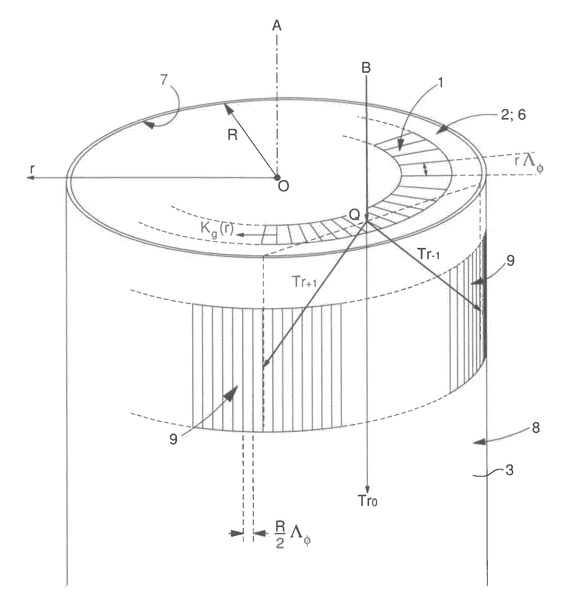
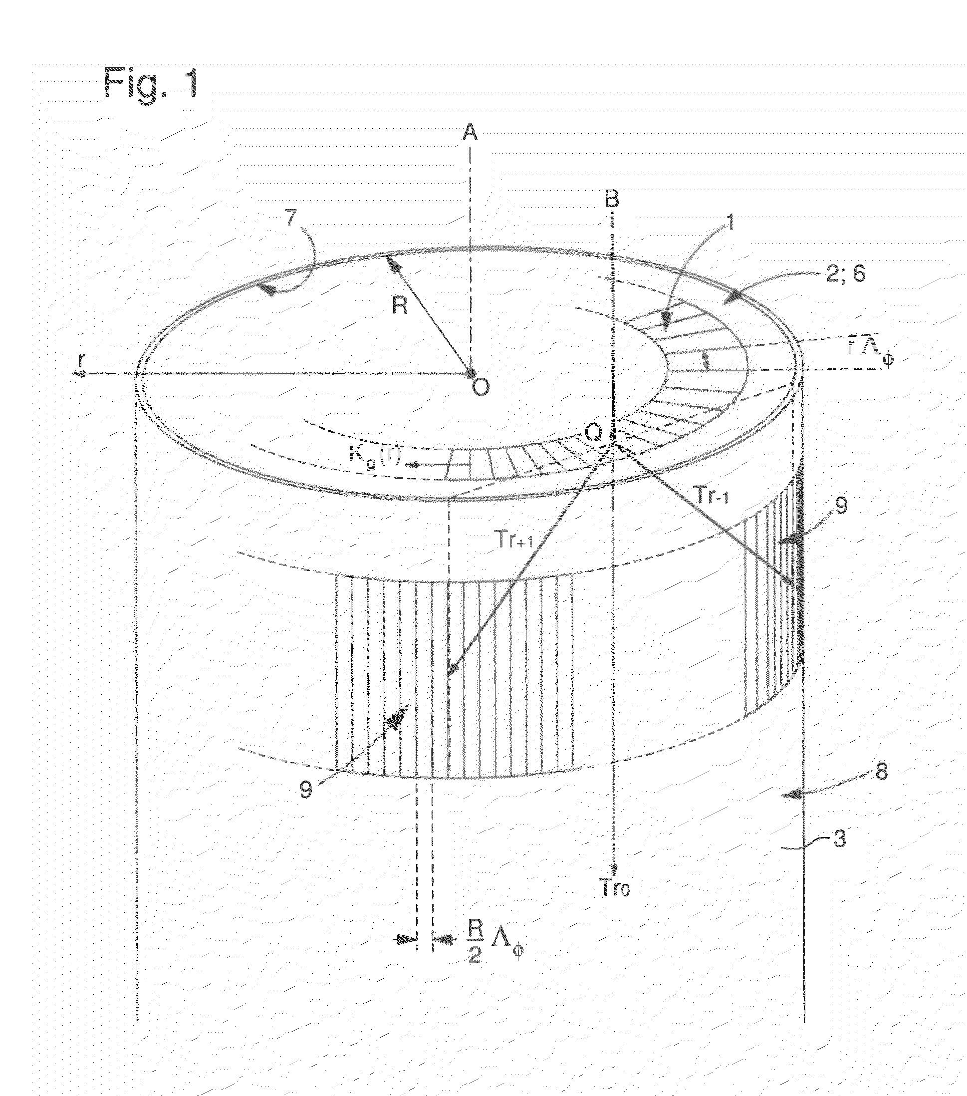
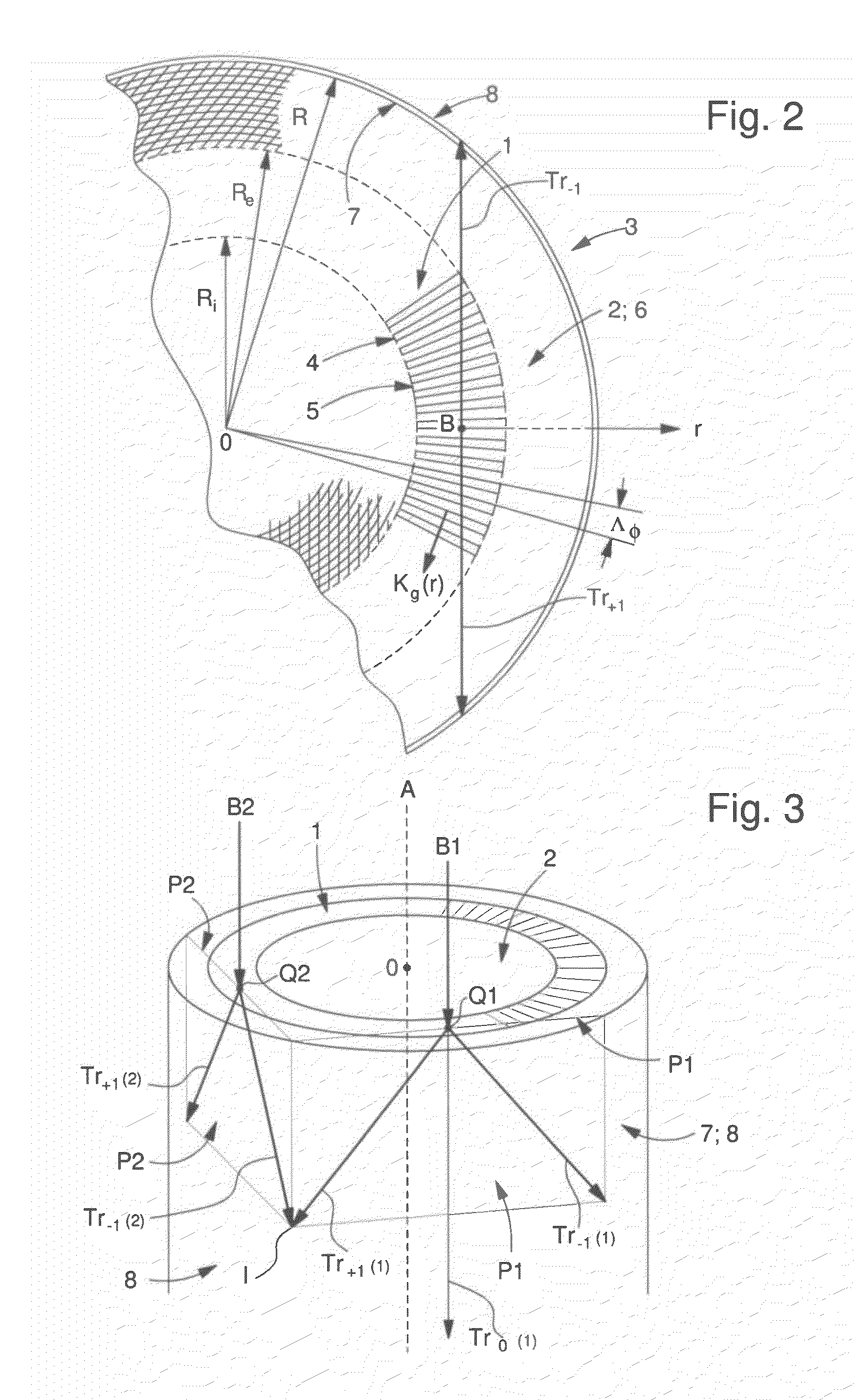
[0030]A first embodiment of the invention will now be described with reference to FIGS. 1 to 3. A binary radial grating 1 of depth tg defined at the upper face 2 of a circularly cylindrical element 3 of radius R, of transparent material of refractive index ns, comprising lines 4 of width wl(r) and grooves 5 of width wg(r) where r is the radial coordinate with origin O. The radial dependence of wl(r) and wg(r) is linear in the radial coordinate r, so is the period Ag(r)=wl(r)+wg(r) of the grating phase mask 1. The dimensionless angular period Λφ is Λg(r) / r. Grating 1 covers an area in the form of a ring of inner radius Ri and external radius Re. Thus, grating 1 defines a planar annular grating with radial lines (annular radial grating).

[0031]There can be several concentric rings of different corrugation period and phase and of different length of lines (and grooves). The center O of the radial grating 1 is the point where all grating lines 4 and grooves 5 intersect. The center O is a...


PUM


Abstract

A phase mask method to geometrically transform and to optically transfer a standard planar radial grating pattern into a cylindrical photoresist pattern at the circularly cylindrical wall of a given element. The planar radial grating pattern can be written with an integer number of lines having strictly constant period without any stitching problem. The photolithographic transfer is made by an illumination device providing a normal incident beam on the phase mask. The annular radial grating diffracts this normal incident beam, formed by plane waves, into two cylindrical waves of the first diffraction order (Tr+1 and Tr−1)) which impinge on the circularly cylindrical wall and interfere in a photoresist layer deposited on the circularly cylindrical wall to give rise to an interferogram.

Description

FIELD OF THE INVENTION[0001]The present invention concerns a fabrication method of cylindrical gratings for possible application in the domain of high resolution optical measurement of rotation, in the domain of spectroscopy and more generally for the domain of diffractive optics involving cylindrical waves.BACKGROUND OF THE INVENTION[0002]The high resolution optical measurement of rotation is usually made by means of a radial diffraction grating of micron scale or submicron scale period in the form of a ring defined at the surface of a rotating encoder disk as shown in document U.S. Pat. No. 5,498,870. The two diffraction orders diffracted in transmission or in reflection, directed along and opposite to the tangential displacement direction at the impact point of an incident beam experience an optical phase shift of opposite sign proportional to the local linear displacement and are recombined by means of a second, non-rotating, radial grating which directs both phase shifted diffr...

Claims


Application Information

Patent Timeline
IPC IPC(8): G03F7/20B29D11/00
CPCG03F1/60G03F7/24G02B5/1857
Inventor TONCHEV, SVETLENPARRIAUX, OLIVIER
Owner SICK AG
Why Eureka
Try Eureka