Renewable Energy Extraction Device

a renewable energy and extraction device technology, applied in the direction of renewable energy generation, electric generator control, rotors, etc., can solve the problems of insufficient support for long-term industrial and technological development, insufficient fossil fuel resources, and high cost of current horizontal axis wind turbines, etc., to achieve efficient extraction of wind energy and efficient extraction of river energy. , the effect of simple and practical design

Active Publication Date: 2013-03-21
SALEHPOOR KARIM
View PDF7 Cites 27 Cited by
  • Summary
  • Abstract
  • Description
  • Claims
  • Application Information

AI Technical Summary

Benefits of technology

[0029]It is still a further object of the present invention to provide a renewable energy extraction device that has a simple and practical design, can be built with no need to sophisticated manufacturing facilities, can be built in different sizes to produce energy for small or large scale applications, can be used as a portable or stationary power generator, built into the ground or floating on water, standalone power generator or a generator to be connected to a power network, can be used to extract wind energy efficiently, can be used to extract energy from river efficiently, and can be used to extract energy from ocean, sea, or a lake efficiently.

Problems solved by technology

Fossil fuels resources are limited and insufficient for the support of long term industrial and technological developments.
On the other hand, uncertainties associated with the supply of fossil fuels have had negative impact on global economy for decades.
Horizontal-axis wind turbines have been used to convert wind energy into electrical power with practical and industrial applications; however, current horizontal-axis wind turbines are expensive and huge in size.
Moreover, transportation to the location of use, installation, and repair & maintenance of such wind turbines is expensive and requires special equipment and techniques which cannot be afforded by individual customers such as ranchers and farmers.
Producing electrical power of industrial and practical importance from water is limited to building hydroelectric power plants, which requires construction of dams over rivers in mountainous areas.
Building a dam is time consuming and expensive.
Moreover, natural disasters, such earthquakes, can cause damage to dams, thus put the adjacent communities in danger.
Water wheels have been used to produce electrical power from rivers, however, at an insignificant rate and with no practical application.
Similarly, there is not any industrial, practical, and economical method or device to capture energy from water in oceans or seas at a significant rate.
Moreover, as the entire paddle wheel electric generation device is mounted and supported on two inflatable tubes, indicates that this system can be used only for small paddle wheels thus it cannot be used for large scale power generation.
Furthermore, this patent claims only capturing energy of the naturally hard-flowing streams; it does not have a claim to generate a hard-flowing stream before capturing its energy.
Finally, this patent does not claim any method to generate a hard-flowing stream before capturing water energy.
There is not any screening means to protect the paddle wheel electric generation device against possible floating objects carrying by the stream.
Also, there is not any means of shutting down the paddle wheel electric generation device for repair and maintenance periods.
This is in violation of engineering practice and is a serious safety issue as the current carrying cable may come into physical contact with the main drive shaft electrically, thus with all the components of the paddle wheel electric generation device if these components are made from metal.
These features, in addition to routing the control and transmission lines under the water, make the cost of the power that can be generated by a portable device expensive and also necessitate some degree of technical expertise to operate and maintain the device continuously.
Moreover, having the dynamo housing and its supporting radial vanes in water flow path have a negative impact on water velocity flowing through the device.
Use of multiple paddle wheels makes the water powered electric generator expensive for the amount of electricity that can be produced.
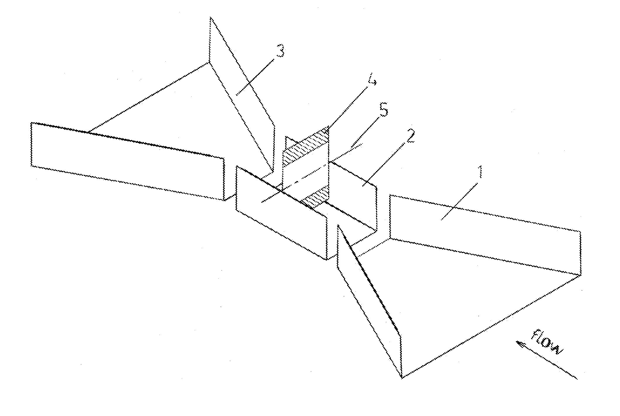
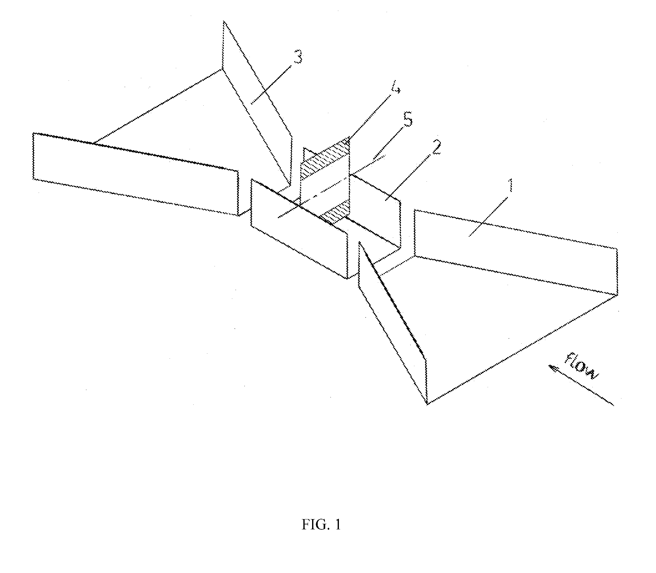
While concentrating flow by narrowing the flow channel has not been included in the claim, it is suggested to narrow the flow channel only by a factor of two; if the water powered electric generator is intended to cover the entire river span, the throat size and the width of each paddle wheel become as half as the river span, making the device an impractical option.
Also, endless belts, that are used to transmit power, can transmit a limited power, making the water powered electric generator inappropriate for large scale power generation.
On the other hand, in rivers with ordinary water velocities, a single unit with a small narrowing ratio of two cannot produce sufficient electric power even for individual families.
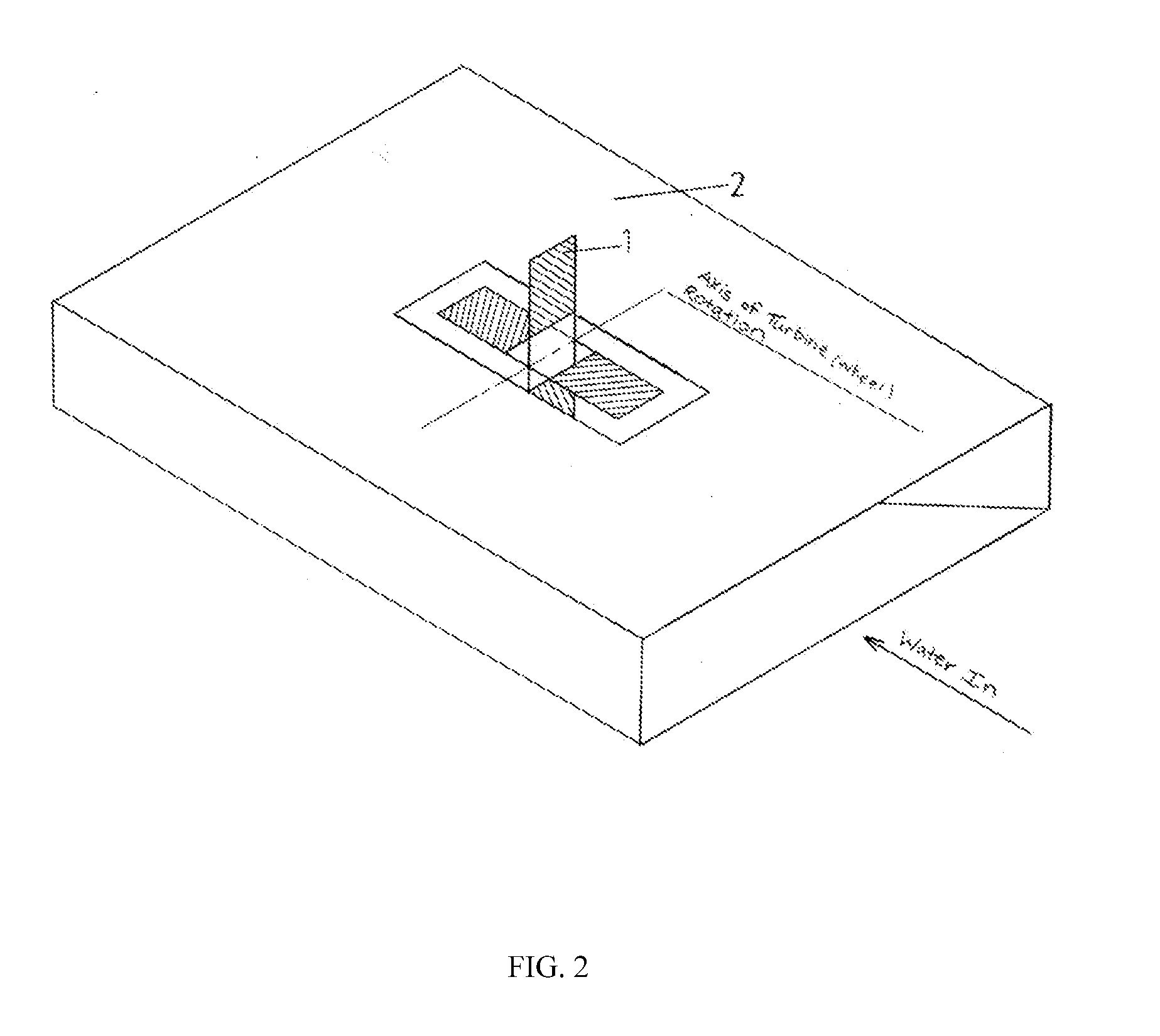
Moreover, the water powered electric generator is floating in water, thus it does not take advantage of the total depth of the running water.
There is not any screening component, thus objects floating in water can damage paddle wheels and disrupt power generation.
As a result, the angular ducts will have a negative impact on function of the device.
Therefore, this device is expensive, complicated, cannot function without frequent disruption, and is not appropriate for large scale power generation.
Structure of the water wheel electric generation device, described above, is impractical for power generation at small scale.
On the other hand, the device does not have means of directing large amounts of flowing water towards the paddles; thus magnitude of the generated power can be increased only by increasing the paddle size.
Therefore the water wheel electric generation device is not practical and appropriate for power generation at large scale either.
Also, the device is not equipped with any means for shutting down for repair and maintenance intervals.
The wave and current operated power generating device, described above, has a complex structure, it is impractical, and is too expensive to be used for power generation at small scale for individual families.
The device, therefore, lacks means of directing a large amount of water towards the paddle wheel, thus it cannot produce electrical power at large scale with a practical paddle wheel size.
Therefore the wave motor is not practical and appropriate for power generation at large scale.
This results in different rotational speeds of rotors.
The gear box will not function properly if rotors intend to rotate the single gear at different speeds.
The vertical multi-phased wind turbine system, described above, has a complex design and cannot result in a practical product.
The targeted produced power is limited to 50 kW of power, thus it is not intended for large scale power generation.
This makes the above method and apparatus impractical.
This is another weakness of the above patent as there is a practical limit on the size of the diameter of the single piston which makes this patent not suitable for energy production at a significant rate.
Unless the size of the drain is very large, the downward stroke of the piston will be very slow, which will be a limiting factor on the magnitude of the stroke.
Therefore, this generator cannot generate power at a significant rate.
The used arrangement, while results in a unidirectional rotation of the power shaft, makes the power shaft to come to a stop each time that wheel's direction of rotation changes.
Therefore, the rotational speed of the power shaft oscillates between zero and a maximum value making the horizontal motion wave power generator inefficient in capturing wave energy.
Further, the horizontal motion wave power generator is practical only for use in the ocean shore and not for deep water.

Method used


Image

  • Renewable Energy Extraction Device
  • Renewable Energy Extraction Device
  • Renewable Energy Extraction Device

Examples


embodiment

10. River Water Embodiment

[0168]FIG. 20 shows top view of a simple renewable energy extraction device (not all components are shown) that can be used for a large river, utilizing multiple high-speed flow compartments with multiple energy extraction components (paddle wheels or water turbines) with a single large inlet and exit compartments. Rivers with large flow rates carry a large amount of extractable energy and may require more than one energy extraction component (paddle wheel or water turbine) with realistic size. Therefore, instead of using multiple renewable energy extraction devices on span of a large river, one renewable energy extraction device with single inlet and exit compartments but with multiple high-speed flow compartments and multiple energy extraction components (paddle wheels or water turbines) may be used to extract water energy in large rivers. Each of the single inlet and exit compartments are wide enough to cover the entire river span, as desired.

[0169]Refer...


PUM


Abstract

Disclosed is a renewable energy extraction device and methods for producing renewable energy from flowing air or water. The renewable energy extraction device captures a relatively large amount of flowing water or atmospheric air and increases speed of the captured water or air by decreasing flow cross sectional area in the flow direction. An energy extraction component is used to extract energy of the high-speed water or air and convert it to rotational mechanical energy on a power shaft. A rotation direction control mechanism is used to make the power shaft always rotate in one direction, without coming to a stop, for ocean applications. The mechanical energy of the power shaft is transmitted to an electric generator, pump, compressor, or any other rotary equipment. After extraction of its energy, the captured air or water is released to its original source at a downstream location.

Description

CROSS REFERENCE TO RELATED APPLICATIONS[0001]This Application claims Priority of Patent Application Ser. No. 61 / 627,069 filed on Sep. 17, 2011.BACKGROUND OF THE INVENTION[0002]1. Field of the Invention[0003]The present invention relates to a renewable energy extraction device for water or wind applications. The renewable energy extraction device captures a relatively large amounts of flowing water (from ocean, sea, lake, pond, river, stream, ditch, or a canal) or atmospheric air (wind) and increases speed of the captured water or air by decreasing flow cross sectional area in the flow direction. Screen(s) or screening device(s) are used to remove any floating and undesired object from the captured water or air. A relatively small energy extraction component is used to extract energy of the high-speed water or air and convert it to rotational mechanical energy on a rotating shaft (power shaft). A rotation direction control mechanism is used to make the power shaft always rotate in on...

Claims


Application Information

Patent Timeline
Patent Type & Authority Applications(United States)
IPC IPC(8): F03B13/00F03D9/00F03B7/00F03B13/26
CPCF03B7/00F03B11/02F03B13/264F05B2210/16Y02E10/226F05B2260/4031F05B2260/421Y02E10/223Y02E10/28F05B2240/133Y02E10/20Y02E10/30
Inventor SALEHPOOR, KARIM
Owner SALEHPOOR KARIM
Why Eureka
Try Eureka