Metal-air battery

a metal-air battery and battery technology, applied in the field of metal-air batteries, can solve the problems of metal-air batteries having a risk of short circuit between their positive and negative electrodes, electrolyte solution may permeate through and leak out of the positive electrodes, and achieve the effect of preventing permeation and leakage and preventing the occurrence of short circuits

Inactive Publication Date: 2013-03-28
HITACHI ZOSEN CORP
View PDF8 Cites 29 Cited by
  • Summary
  • Abstract
  • Description
  • Claims
  • Application Information

AI Technical Summary

Benefits of technology

[0008]The present invention is intended for a metal-air battery, and it is a primary object of the present invention to prevent generation of a metal carbonate on a positive electrode during discharge. Other objects of the present invention are to prevent permeation and leakage of an electrolyte solution into and from the positive electrode and to prevent the occurrence of a short circuit between a negative electrode and an auxiliary electrode.

Problems solved by technology

Metal-air batteries have a risk of a short circuit occurring between their positive and negative electrodes due to local deposition of metals on the negative electrodes during charge.
The metal-air batteries also have a risk that the electrolyte solution may permeate through and leak out of the positive electrodes because the positive electrodes are porous members.
The leakage of the electrolyte solution will considerably reduce battery performance (e.g., battery capacity).
However, even such a metal-air battery has a risk of a short circuit occurring between the negative electrode and the auxiliary electrode due to local deposition of metals on the negative electrode during charge.

Method used


Image

  • Metal-air battery
  • Metal-air battery
  • Metal-air battery

Examples


first embodiment

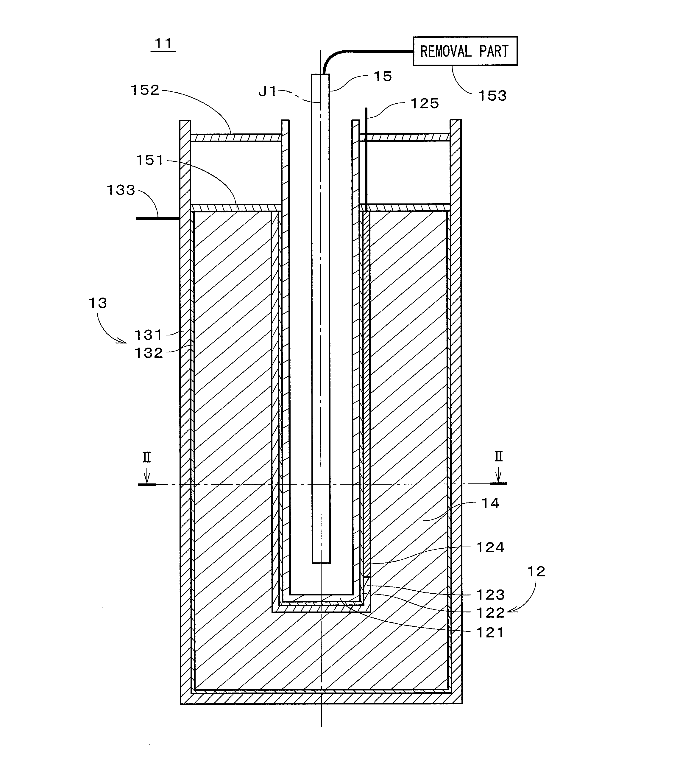
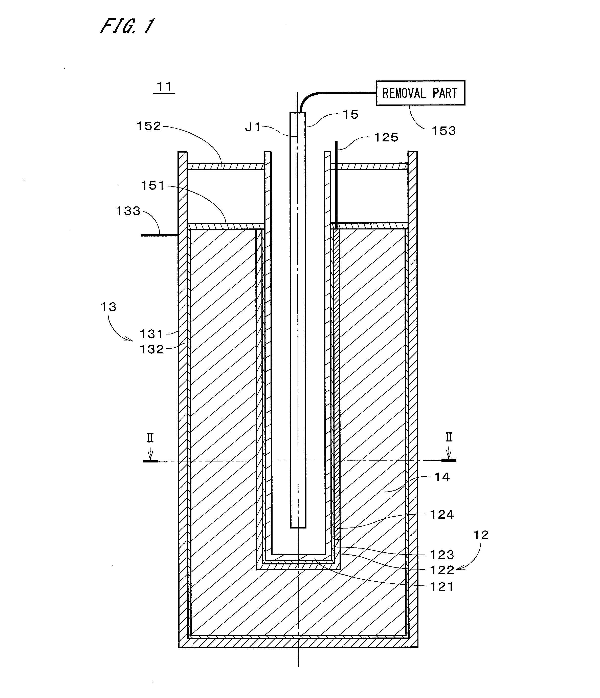
[0036]FIG. 1 is a longitudinal cross-sectional view of a metal-air battery 11 according to the present invention. The metal-air battery 11 has a substantially cylindrical shape, and a cross section of the metal-air battery 11 including a central axis J1 thereof is shown in FIG. 1. FIG. 2 is a transverse cross-sectional view of the metal-air battery 11 taken along line II-II in FIG. 1. As shown inFIGS. 1 and 2, the metal-air battery 11 is a secondary battery that includes a positive electrode 12, a negative electrode 13, an electrolyte layer 14, and an air introduction pipe 15. The air introduction pipe 15, the positive electrode 12, the electrolyte layer 14, and the negative electrode 13 are concentrically disposed in this order from the central axis J1 toward the outside in the radial direction. In other words, the metal-air battery 11 has a substantially cylindrical shape in which the negative electrode 13 is disposed along its outer periphery and the positive electrode 12 is disp...

second embodiment

[0058]The barrier layer 17a is a porous member formed of ceramics, metals, inorganic materials, organic materials, or the like and holds an electrolyte in its pores, the electrolyte allowing lithium ions to selectively pass therethrough. The formation of the barrier layer 17a is carried out by extrusion molding, CIP and firing, HIP, or the like. Reactions during the charge and discharge of the metal-air battery 11b are the same as those of the metal-air battery 11a according to the

[0059]Since the positive electrode 12 of the metal-air battery 11b contains no carbon as in the first and second embodiments, it is possible to prevent the generation of lithium carbonate on the positive electrode 12 during discharge and to thereby reduce the charge voltage of the metal-air battery 11b. Furthermore, providing the barrier layer 17a between the positive electrode 12 and the negative electrode 13 makes it possible to suppress the growth of dendrites on the negative electrode 13 during charge,...

sixth embodiment

[0072]FIG. 8 is a longitudinal cross-sectional view of a metal-air battery 21 according to the present invention. The metal-air battery 21 has a substantially cylindrical shape, and a cross section of the metal-air battery 21 including a central axis J1 thereof is shown in FIG. 8. FIG. 9 is a transverse cross-sectional view of the metal-air battery 21 taken along line IX-IX in FIG. 8. As shown in FIGS. 8 and 9, the metal-air battery 21 is a secondary battery that includes a positive electrode 22, a negative electrode 23, an electrolyte layer 24, and an air introduction pipe 25. The air introduction pipe 25, the positive electrode 22, the electrolyte layer 24, and the negative electrode 23 are concentrically disposed in this order from the central axis J1 toward the outside in the radial direction. In other words, the metal-air battery 21 has a substantially cylindrical shape in which the negative electrode 23 is disposed along its outer periphery and the positive electrode 22 is dis...


PUM

PropertyMeasurementUnit
diameteraaaaaaaaaa
diameteraaaaaaaaaa
diameteraaaaaaaaaa

Abstract

A metal-air battery is a secondary battery that includes a positive electrode, a negative electrode, an electrolyte layer, and an air introduction pipe. The positive electrode is a porous member having a substantially cylindrical bottomed shape and includes a positive electrode supporter made of alumina, a positive electrode conductive layer made of a perovskite type oxide having electrical conductivity, and a positive electrode catalyst layer made of manganese dioxide. The negative electrode includes a negative electrode supporter made of stainless steel and a negative electrode conductive layer made of lithium or a lithium alloy. The metal-air battery can realize the positive electrode that contains no carbon by forming the positive electrode catalyst layer on the positive electrode conductive layer made of a perovskite type oxide. This enables prevention of the generation of lithium carbonate on the positive electrode during discharge, thus reducing the charge voltage of the metal-air battery.

Description

TECHNICAL FIELD[0001]The present invention relates to a metal-air battery.BACKGROUND ART[0002]Conventionally, metal-air batteries that use metals as active materials of their negative electrodes and the oxygen in the air as active materials of their positive electrodes are known. For example, Japanese Patent Application Laid-Open No. 2008-66202 (Document 1) proposes a metal-air battery in which an electrolyte-containing layer is provided between the positive electrode and the negative electrode, wherein an electrolyte of the layer contains ionic liquids, inorganic fine particles, and an electrolyte salt. Japanese Patent Application Laid-Open No. 2009-230981 (Document 2) proposes a metal-air battery in which a positive electrode and a negative electrode are disposed in a non-aqueous electrolyte solution and that is provided with an oxygen pump that supplies the oxygen in the air to the positive electrode via an oxygen-ion conducting solid electrolyte.[0003]In the lithium-air secondar...

Claims


Application Information

Patent Timeline
Patent Type & Authority Applications(United States)
IPC IPC(8): H01M12/06
CPCH01M4/8657H01M4/9016H01M12/08H01M8/22Y02E60/50H01M12/06H01M2004/8689Y02E60/10H01M4/86
Inventor AIZAWA, MASANOBU
Owner HITACHI ZOSEN CORP
Why Eureka
Try Eureka