Ophthalmology appliance for photocoagulation or phototherapy, and method for operating such an appliance

a technology of ophthalmology and photocoagulation, which is applied in the field of ophthalmological devices, can solve the problems of scarring, conventional photocoagulation, and relatively time-consuming treatment, and achieve the effect of shortening the time and reducing the expenditur

Inactive Publication Date: 2013-04-04
CARL ZEISS MEDITEC AG
View PDF7 Cites 14 Cited by
  • Summary
  • Abstract
  • Description
  • Claims
  • Application Information

AI Technical Summary

Benefits of technology

[0010]The problem addressed by the invention is that of improving a device of the type initially described in such a way that photocoagulation or phototherapy is possible at low expenditures in a shorter period of time.

Problems solved by technology

Through thermal conduction, the adjacent tissue is also heated, causing it to become scarred.
Conventional photocoagulation is disadvantageous due to high costs for a laser beam source with a comparatively high beam quality in order to be able to couple the radiation into an optical fiber with a typical diameter of 50 μm.
In addition, the treatment is relatively time-consuming, usually 20 to 30 minutes, due to the manual generation of a large number of individual coagulation spots, which is uncomfortable for the patient.
This type of laser coagulation is disadvantageous because the sequence of successive scanning and irradiation of a coagulation pattern can last up to 0.5 sec during which the patient's eye can move, resulting in a possible misalignment within the pattern.
Moreover, the system of the mostly electromechanical beam-deflecting devices is costly and high-maintenance due to signs of wear.

Method used


Image

  • Ophthalmology appliance for photocoagulation or phototherapy, and method for operating such an appliance
  • Ophthalmology appliance for photocoagulation or phototherapy, and method for operating such an appliance
  • Ophthalmology appliance for photocoagulation or phototherapy, and method for operating such an appliance

Examples


Embodiment Construction

[0068]Corresponding components have the same reference signs in all drawings.

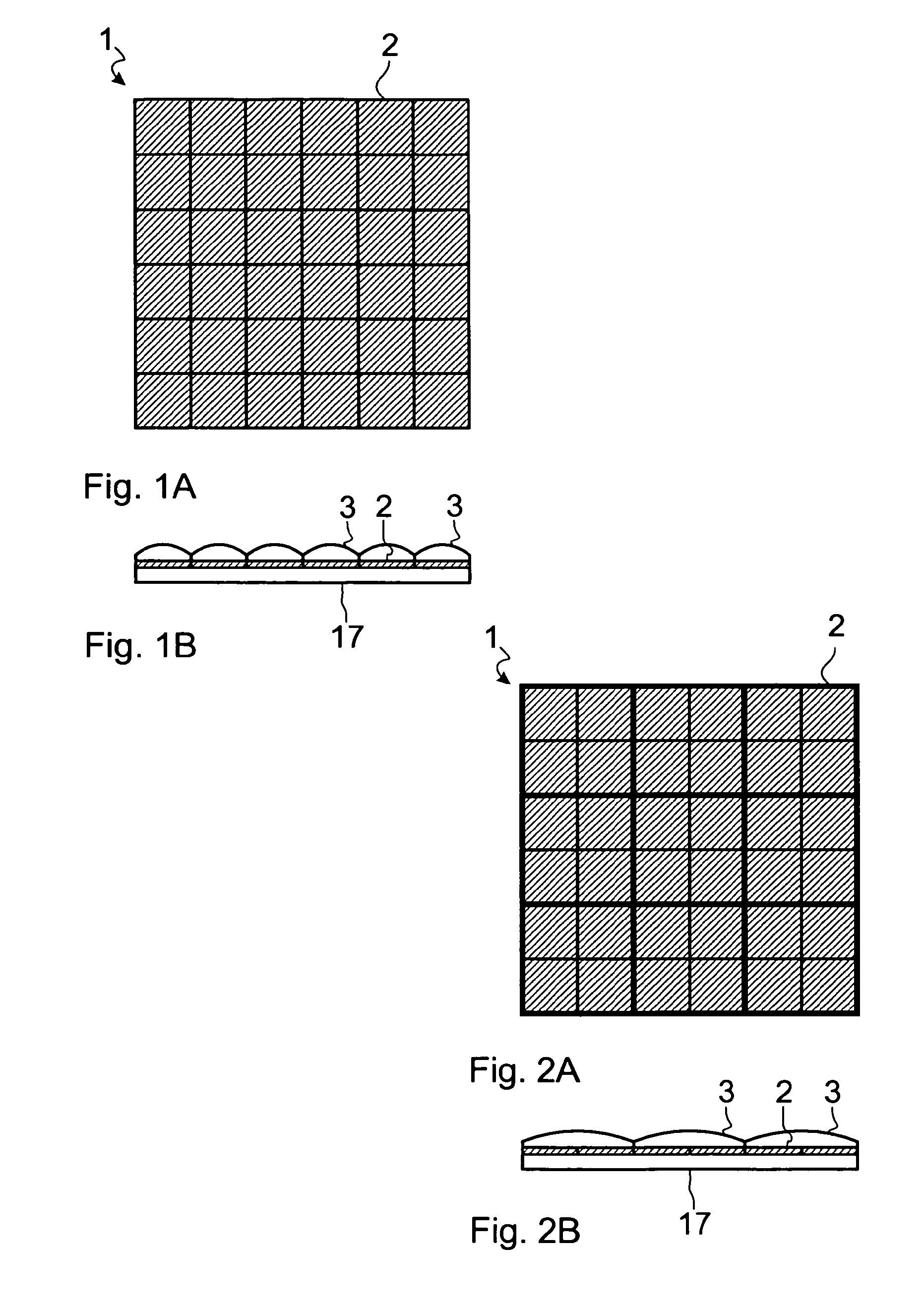
[0069]FIG. 1 schematically depicts a light-emitting diode array as structured radiation source 1 with, e.g., 6×6 single emitters 2 which emit light in a spectral range of, e.g. 511 nm to 553 nm (central wavelength 532 nm), identical for all emitters 2. According to the invention, the radiation source 1 can be used as main component of a coagulator (not depicted). The coagulator can be part of a more complex device (not depicted). The therapy beam path and the treatment region are not depicted for reasons of simplification.

[0070]The single emitters 2 are semiconductor light-emitting diodes which are arranged equidistantly on a joint substrate 17. In detailed FIG. 1A, the matrix 1 is depicted as topview, detailed FIG. 1B shows the profile of said matrix. In the profile, the 36 micro-optics 3 which are directly connected to the matrix substrate 17 are shown in an example form as an integrally designed microlen...


PUM


Abstract

A device intended to permit photocoagulation or phototherapy at low cost and in a shorter time. For this purpose, an ophthalmology appliance includes a radiation source having several discrete individual emitters. The therapy beam path leading from the radiation source to the treatment area projects an image of at least respective portions of different individual emitters simultaneously onto surfaces spaced apart from each other in the treatment area. This permits simultaneous generation of several coagulation foci and dispenses with the need for electromechanical beam-deflecting units, which permits a shorter treatment time.

Description

PRIORITY CLAIM[0001]The present application is a National Phase entry of PCT Application No. PCT / EP2011 / 002648, filed May 28, 2011, which claims priority from German Application No. 10 2010 022 760.9, filed Jun. 4, 2010, the disclosures of which are hereby incorporated by reference herein in their entirety.FIELD OF THE INVENTION[0002]The invention relates to an ophthalmological device having a radiation source for photocoagulation or phototherapy of tissue, particularly a retina of an eye, a therapy beam path extending from the radiation source to a treatment region, and an observation beam path.BACKGROUND[0003]Light coagulation or photocoagulation is a therapy in use since 1949 for different diseases of the retina, for example, retinal detachment. While xenon high-pressure lamps and even sunlight were initially used, lasers which emit continuous waves (cw) are normally used today as light source. Photocoagulation is then called laser coagulation.[0004]At first, the eye is placed in...

Claims


Application Information

Patent Timeline
Patent Type & Authority Applications(United States)
IPC IPC(8): A61F9/008A61F9/007
CPCA61F9/008A61F9/00821A61F9/007A61F2009/00863A61F9/00823
Inventor DICK, MANFREDDENNER, RENEKUNATH-FANDREI, GERALD
Owner CARL ZEISS MEDITEC AG
Why Eureka
Try Eureka