Dry etching method for metal film

a metal film and etching technology, applied in the direction of coating by sputtering, decorative arts, coating carrier supports, etc., can solve the problems of difficult to obtain vertical sidewalls, difficult to obtain selectivity between mask layers and pt—mn layers, and accelerate corrosion of components of etching apparatuses

Active Publication Date: 2013-04-25
TOKYO ELECTRON LTD
View PDF3 Cites 164 Cited by
  • Summary
  • Abstract
  • Description
  • Claims
  • Application Information

AI Technical Summary

Benefits of technology

[0007]In view of the above, the present invention provides a dry etching method for a metal film capable of making a sidewall of a hole or trench more vertical without using a halogen gas.

Problems solved by technology

Therefore, it is difficult to obtain selectivity between the mask layer and the Pt—Mn layer.
Since, however, the halogen gas generates strong acids, corrosion of components of an etching apparatus is accelerated.
Further, it is difficult to obtain a vertical sidewall, and the hole or the trench becomes tapered in shape.

Method used


Image

  • Dry etching method for metal film
  • Dry etching method for metal film
  • Dry etching method for metal film

Examples


Embodiment Construction

[0014]Hereinafter, an embodiment of the present invention will be described with reference to the accompanying drawings.

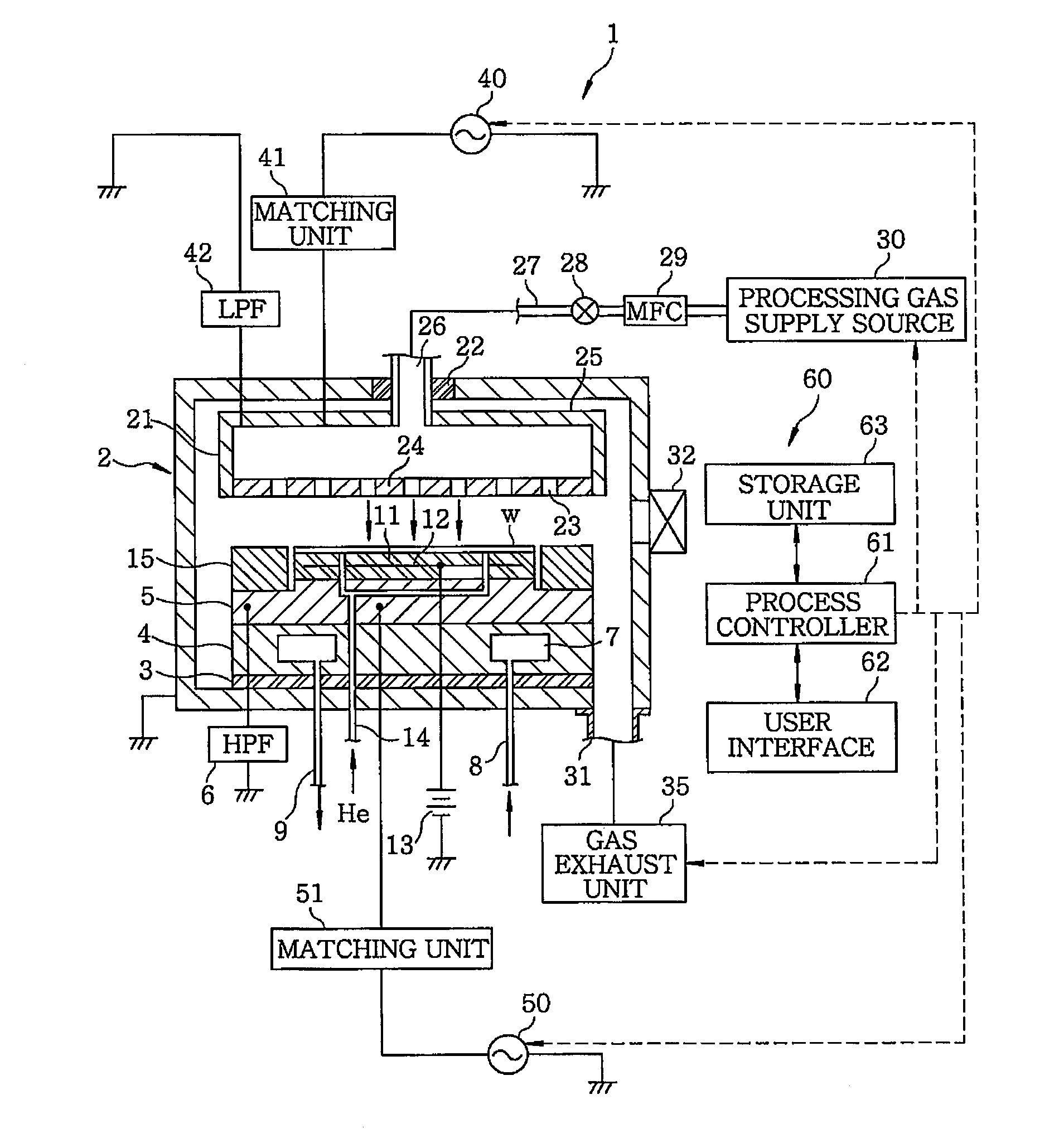
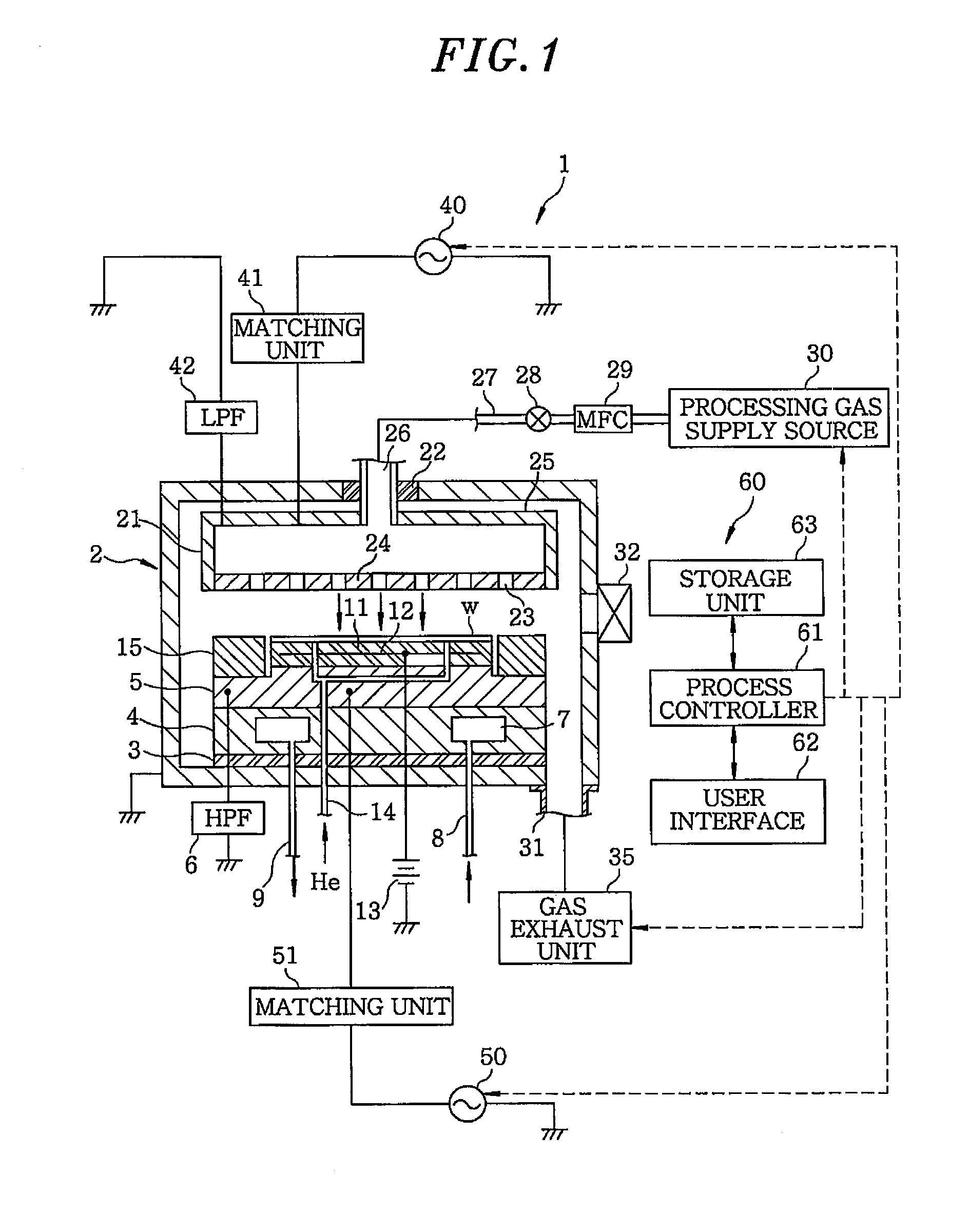
[0015]First, a configuration example of a plasma etching apparatus in accordance with an embodiment of a dry etching method for a metal film of the present invention will be explained. FIG. 1 schematically shows a cross section of a plasma etching apparatus used for dry etching of a metal film.

[0016]A plasma etching apparatus 1 includes a grounded cylindrical processing chamber 2 made of, e.g., aluminum having an anodically anodized surface. An approximately columnar susceptor support 4 for mounting thereon a target object, e.g., a semiconductor wafer W, is provided at a bottom portion of the processing chamber 2 via an insulating plate 3 such as ceramic or the like. Moreover, a susceptor (mounting table) 5, serving as a lower electrode, is provided above the susceptor support 4. The susceptor 5 is connected to a HPF (High Pass Filter) 6.

[0017]The susceptor support...


PUM

PropertyMeasurementUnit
pressureaaaaaaaaaa
DC voltageaaaaaaaaaa
frequencyaaaaaaaaaa

Abstract

A method for performing dry etching on a metal film containing Pt via a mask layer includes performing dry etching on the metal film by generating a plasma of an etching gas including a gaseous mixture of H2 gas, CO2 gas, methane gas and rare gas. With the dry etching method, it is possible to make a vertical sidewall of a hole or trench more vertical without using a halogen gas.

Description

CROSS-REFERENCE TO RELATED APPLICATION[0001]This application claims priority to Japanese Patent Application No. 2011-230764 filed on Oct. 20, 2011 and U.S. Provisional Application No. 61 / 557,465 filed on Nov. 9, 2011, the entire contents of which are incorporated herein by reference.FIELD OF THE INVENTION[0002]The present invention relates to a dry etching method for a metal film.BACKGROUND OF THE INVENTION[0003]A magnetic storage device that stores therein information by using magnetization reversal by a magnetic field of an electric current is manufactured by using a semiconductor wafer in which various layers are laminated and etched in desired patterns. One of the layers of the magnetic storage device is a Pt—Mn layer containing Pt as a magnetic material. However, Pt is known as a material that is hardly etched.[0004]As for an etching method for the Pt—Mn layer, there is known, a method for physically etching the Pt—Mn layer by ion milling, e.g., by sputtering using Ar positive ...

Claims


Application Information

Patent Timeline
Patent Type & Authority Applications(United States)
IPC IPC(8): C23F1/02
CPCH01L43/12G11B5/851C23F4/00H10N50/01C23F1/12H01L21/3065
Inventor NISHIMURA, EIICHISONE, TAKASHI
Owner TOKYO ELECTRON LTD
Why Eureka
Try Eureka