
Process for Producing Ammonia Synthesis Gas

a technology of ammonia synthesis and ammonia gas, which is applied in the direction of hydrogen separation using solid contact, chemical apparatus and processes, and bulk chemical production, etc. it can solve the negative impact of reforming itself, large volumetric flow rate, and large equipment size, so as to reduce the overall volumetric flow rate of syngas production, reduce the flow rate of substantially inert steam, and increase the flow rate of useful gas

Active Publication Date: 2013-04-25
CASALE SA
View PDF20 Cites 6 Cited by
  • Summary
  • Abstract
  • Description
  • Claims
  • Application Information

AI Technical Summary

Benefits of technology

The invention is about a process for upgrading an ammonia plant by reducing the ratio of steam to carbon dioxide in the primary reformer. This reduces the amount of inert steam and allows for a higher flow rate of useful gas, which can increase the production capacity of the plant. The purification of the syngas can also be improved through techniques such as cryogenic separation and adsorption. The overall effect of the invention is to increase the efficiency and production capacity of the ammonia plant.

Problems solved by technology

However, a large amount of steam causes the following drawbacks: excess steam causes a larger volumetric flow rate, which calls for larger and more expensive equipments; excess steam moreover is inert to the reforming and then has a negative impact on the efficiency of the reforming itself.

Method used


Image

  • Process for Producing Ammonia Synthesis Gas
  • Process for Producing Ammonia Synthesis Gas

Examples


examples

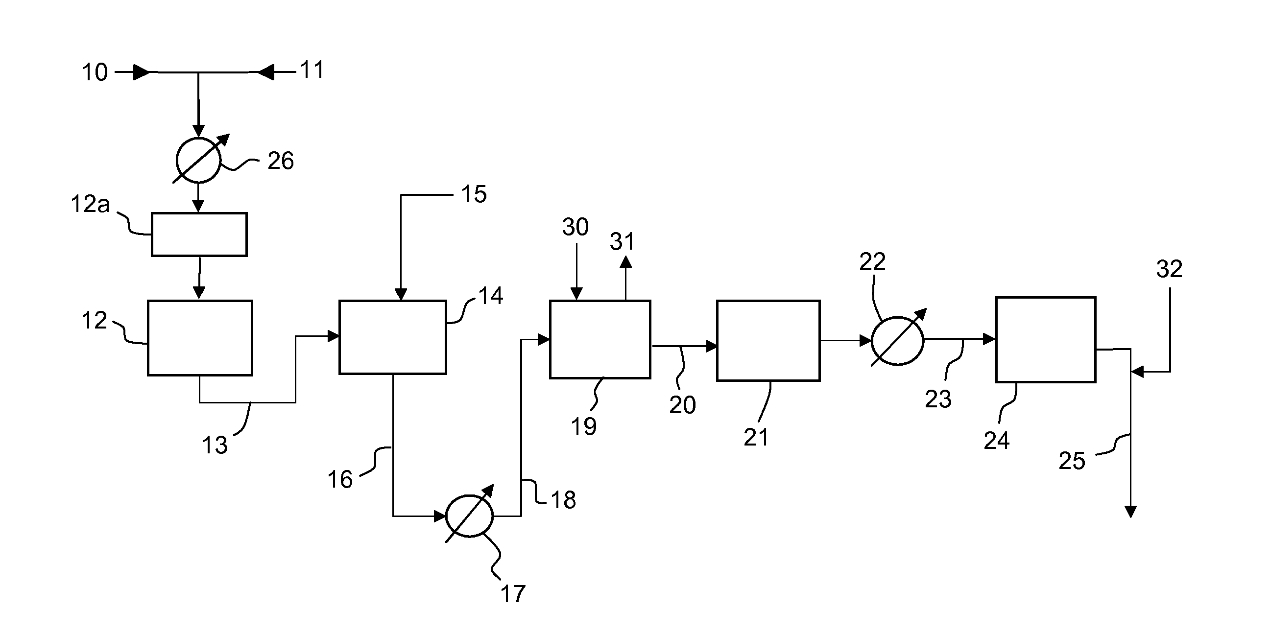
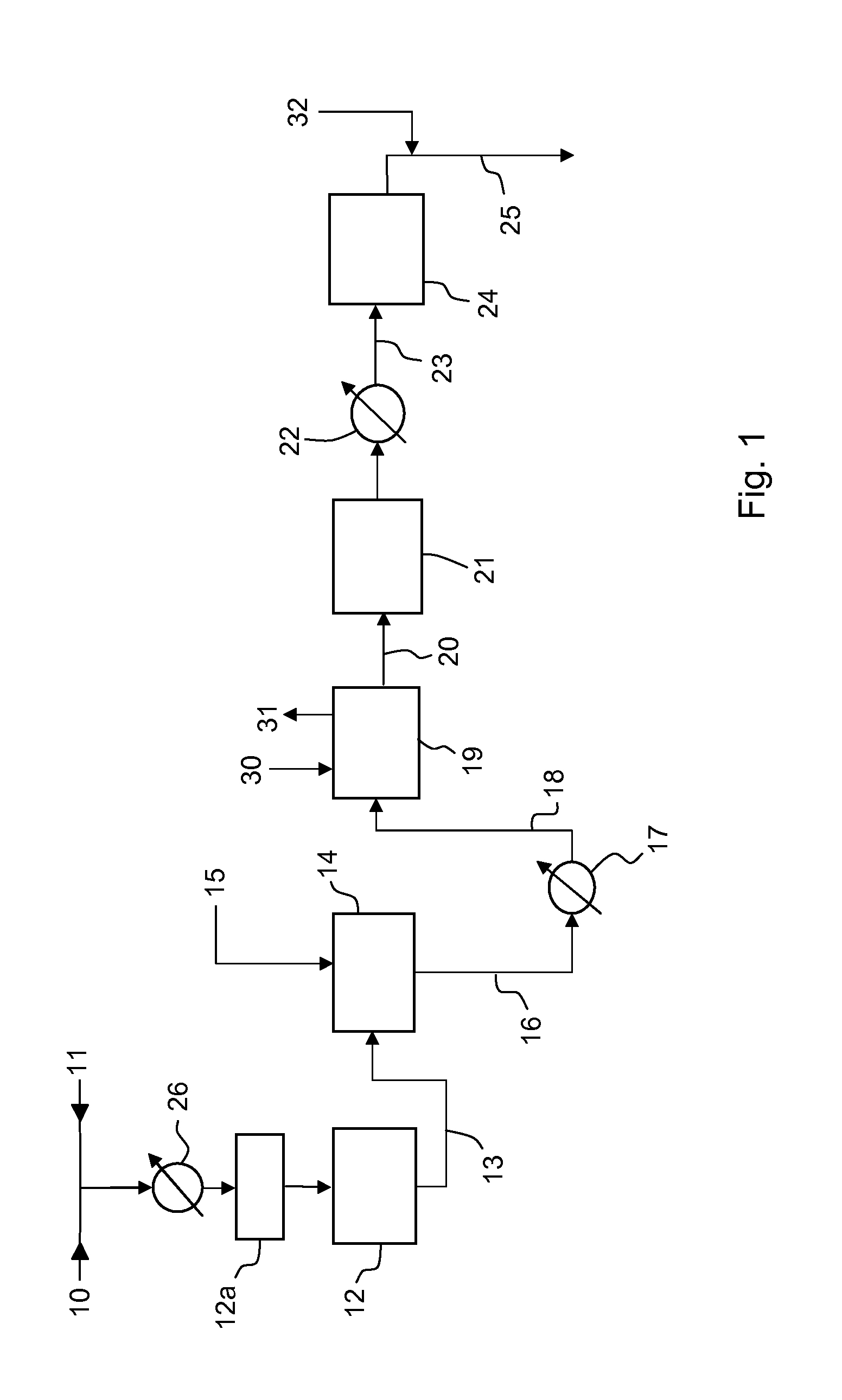
[0049]A conventional ammonia plant rated at 1700 MTD (metric tons per day) of ammonia is revamped according to the following embodiments of the invention:

[0050]A) reduction of SC ratio in the primary reformer to about 1.5 and installation of a pre-refomer such as 12a in FIG. 1;

[0051]B) same as A with further step of providing excess air to the secondary reformer;

[0052]C) same as A with further step of providing enriched air to the secondary reformer;

[0053]D) same as A with further step of providing pure (>95%) oxygen to the secondary reformer.

[0054]The production rate can be increased to 2150 MTD (+26%) in case A; 2200 MTD (+29%) in case B; 2500 MTD (+47%) in case C and 2700 MTD (+59%) in case D. The specific energy consumption (Gcal per MTD), including energy consumed for air separation and production of oxygen for air enrichment (case C) or pure oxygen feed (case D), is reduced by about 0.1 Gcal / MTD in case A; about 0.2 Gcal / MTD in case B and about 0.5 Gcal / MTD in cases C and D.


PUM

PropertyMeasurementUnit
temperatureaaaaaaaaaa

Abstract

A process for producing ammonia synthesis gas from a hydrocarbon-containing feedstock, with steps of primary reforming, secondary reforming with an oxidant stream, and further treatment of the synthesis gas including shift, removal of carbon dioxide and methanation, wherein the synthesis gas delivered by secondary reforming is subject to a medium-temperature shift (MTS) at a temperature between 200 and 350° C., and primary reforming is operated with a steam-to-carbon ratio lower than 2. A corresponding method for revamping an ammonia plant is disclosed, where an existing HTS reactor is modified to operate at medium temperature, or replaced with a new MTS reactor, and the steam-to-carbon ratio in the primary reformer is lowered to a value in the range 1-5-2, thus reducing inert steam in the flow rate trough the equipments of the front-end.

Description

FIELD OF THE INVENTION[0001]The invention relates to reforming of hydrocarbons for the preparation of a synthesis gas, also named syngas, for the production of ammonia.PRIOR ART[0002]The synthesis of ammonia (NH3) requires a synthesis gas comprising hydrogen (H2) and nitrogen (N2) in a suitable ratio of about 3:1. The term ammonia syngas will be used with reference to a synthesis gas with the above composition.[0003]It is known to produce said syngas from the reforming of a hydrocarbon (HC) feedstock containing methane. Reforming takes place in a primary reformer and then in a secondary reformer. Usually, the feedstock and a suitable amount of steam are admitted into a primary reformer, where methane is converted in a mixture of carbon monoxide, carbon dioxide and hydrogen by passage over a suitable catalyst; the secondary reformer receives the gas product delivered by the primary reformer, and an air flow. The reformed gas exiting the secondary reformer is then purified, especially...

Claims


Application Information

Patent Timeline
Patent Type & Authority Applications(United States)
IPC IPC(8): C01B3/02
CPCC01B3/025C01B2203/146C01B3/48C01B3/506C01B3/56C01B2203/0233C01B2203/0244C01B2203/0283C01B2203/0288C01B2203/043C01B2203/0445C01B2203/046C01B2203/0475C01B2203/068C01B2203/0883C01B2203/1235C01B2203/141C01B2203/143C01B3/382Y02P20/52
Inventor FILIPPI, ERMANNOBARATTO, FRANCESCOPANZA, SERGIOOSTUNI, RAFFAELE
Owner CASALE SA
Learn More