
Making a lithium ion battery separator

a lithium ion battery and separator technology, applied in the direction of cell components, cell component details, electrochemical generators, etc., can solve the problems of polyolefin separators that are susceptible to certain performance declines, electrochemical cells that are short-circuited, polyolefin separators that are shrinking, softening and even melting, etc., and achieves the effect of convenient drying

Active Publication Date: 2013-05-23
GM GLOBAL TECH OPERATIONS LLC
View PDF4 Cites 28 Cited by
  • Summary
  • Abstract
  • Description
  • Claims
  • Application Information

AI Technical Summary

Benefits of technology

The patent describes a process to remove a solvent from a solid polymer precipitate by using a non-solvent. This process helps to dry the polymer and makes it easier to prepare a single phase polymer solution. The non-solvent used in this process may be the same or different from the non-solvent used to prepare the polymer solution. The technical effect of this process is to provide a more efficient and effective method for removing solvents from polymers.

Problems solved by technology

A polyolefin separator, however, is potentially susceptible to certain performance declines when heated excessively.
Exposure of the electrochemical battery cell to temperatures of 80° C. and above can cause the polyolefin separator to shrink, soften, and even melt.
The physical distortion of the polyolefin separator may ultimately permit direct electrical contact between the negative and positive electrodes and cause the electrochemical cell to short-circuit.
This inability of a polyolefin separator to maintain thermal stability at temperatures exceeding 80° C. for prolonged periods is a potential concern for some lithium ion battery applications.
But the separator fabrication methods often used for polyolefin separators generally cannot provide these types of polymers with a sufficient and uniform porosity across their thickness at reasonable costs.
The stretching techniques often employed in conventional polyolefin separator manufacturing processes has also been shown to adversely affect the dimensional stability of engineering polymer separators at elevated temperatures above 80° C. and, more noticeably, above 100° C. A fabrication method that can reliably produce, from a variety of engineering polymers, a thermally stable polymer separator having a generally uniform network of pores defined across its thickness is therefore needed.

Method used


Image

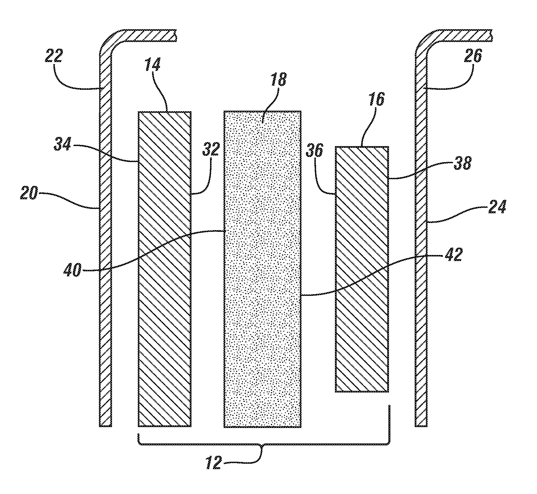
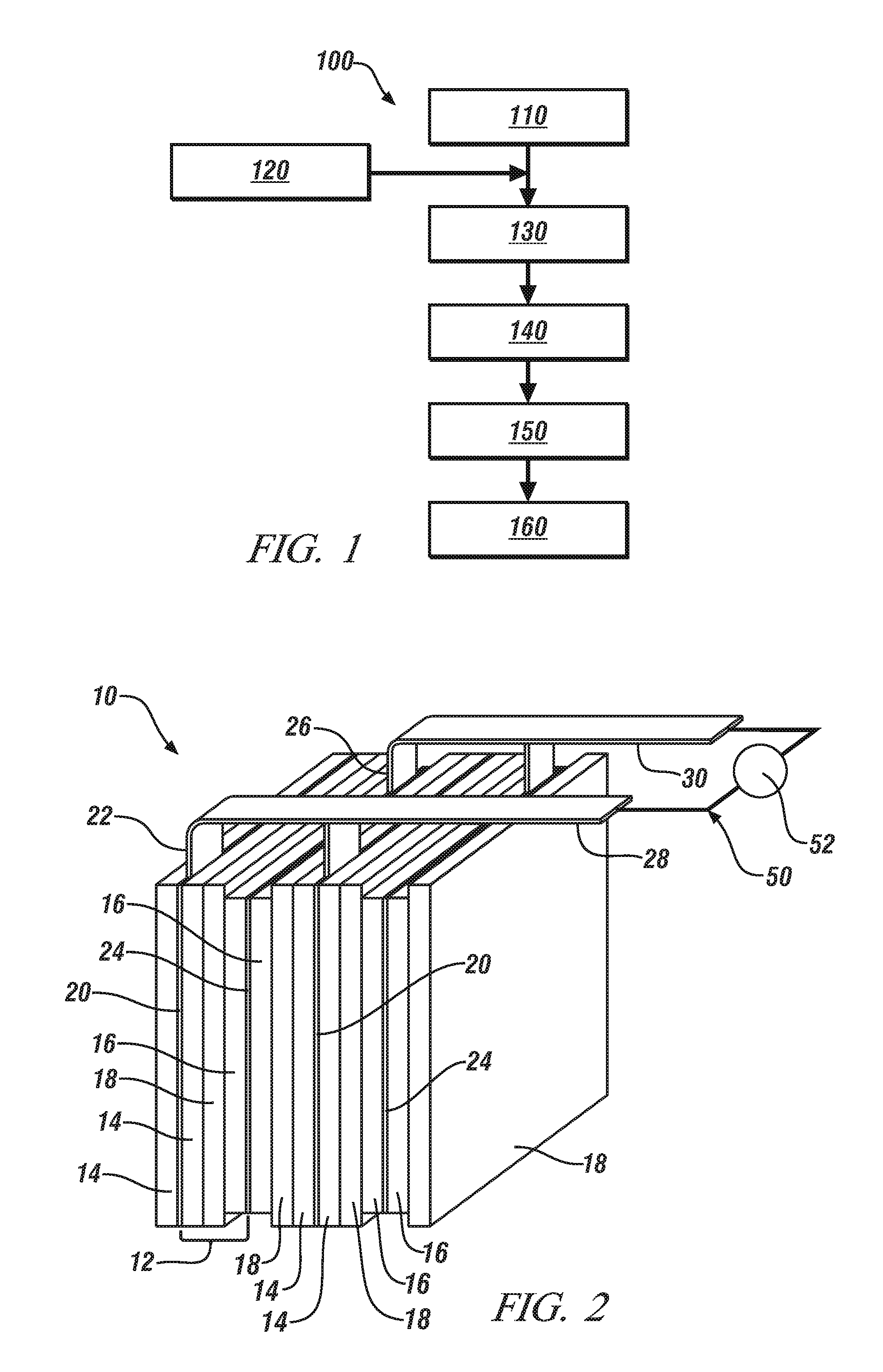
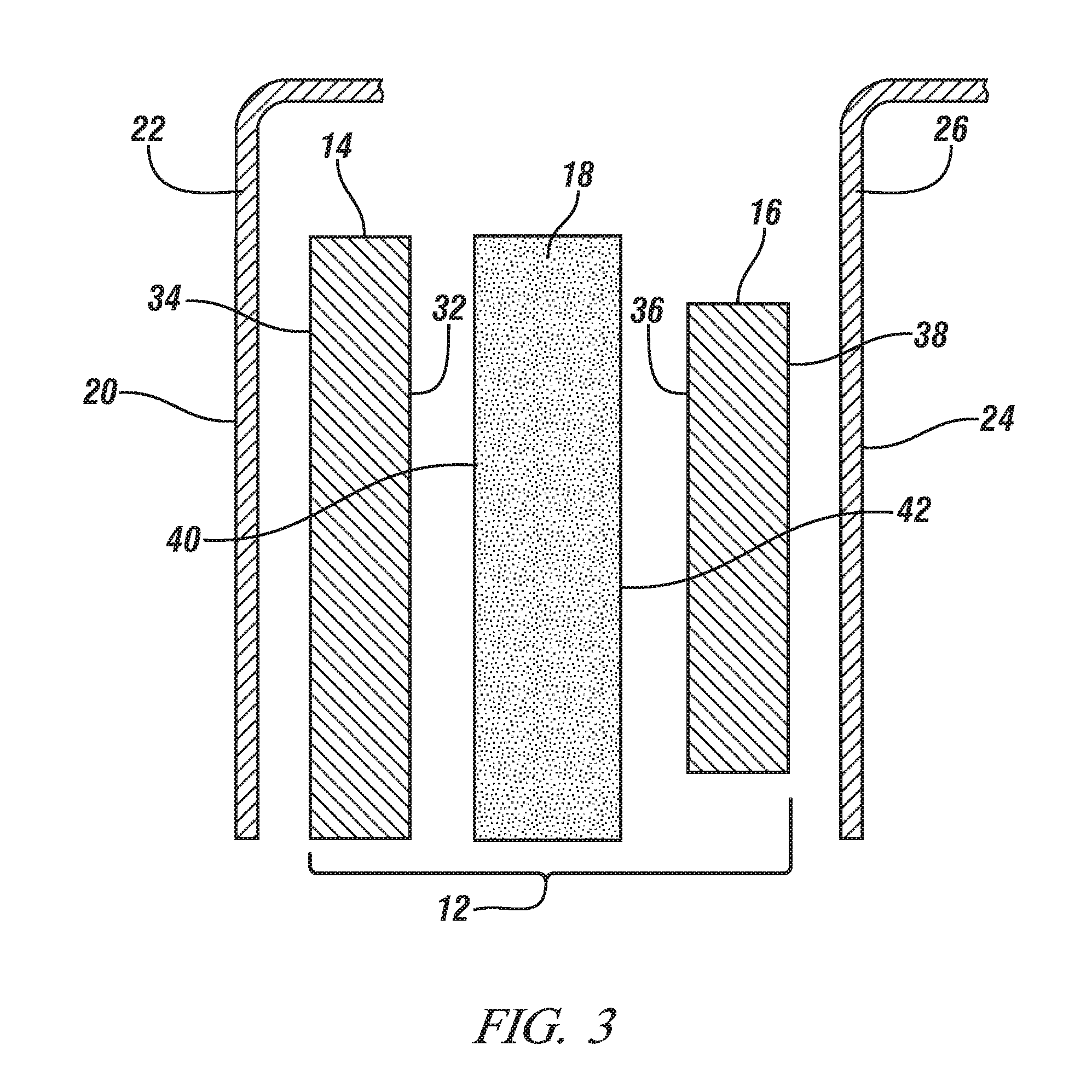
  • Making a lithium ion battery separator
  • Making a lithium ion battery separator
  • Making a lithium ion battery separator

Examples


example

[0045]This Example demonstrates the lithium ionic conductivity of a porous polymer separator made according to the thermally-induced phase separation method described above in comparison to a conventional monolayer polypropylene lithium ion battery separator obtained from Celgard, LLC (Charlotte, N.C.). The porous polymer separator comprises a PEI polymer matrix. This particular separator is referred to in the remainder of this Example as the “Separator A” for brevity.

[0046]Separator A was formed by a thermally-induced phase separation method in which polyetherimide (PEI) was dissolved in a miscible mixture of, by weight, 95 parts N-methyl-2-pyrrolidone (NMP) and 5 parts water at 50° C. to form a single phase polymer solution that contained 20 wt. % PEI. Here, NMP is the real polymer solvent and water is the polymer non-solvent. Particles of Aerosil R805 (hydrophobic-treated fumed silica particles) were then added to the single phase polymer solution. The amount of these particles a...


PUM

PropertyMeasurementUnit
thicknessaaaaaaaaaa
particle diametersaaaaaaaaaa
wt. %aaaaaaaaaa

Abstract

A porous polymer separator for use in a lithium ion battery is formed by a temperature-induced phase separation method. The porous polymer separator includes a polymer matrix having opposed major faces and a network of pore openings that extends between the major faces and permits intrusion of a lithium-ion conducting electrolyte solution. As part of the temperature-induced phase separation method, a single phase polymer solution that includes a polymer material dissolved in a miscible mixture of a real polymer solvent and a polymer non-solvent is prepared at an elevated temperature above room temperature. A film is then formed from the single phase polymer solution and cooled to phase-separate the polymer material into a solid polymer precipitate. Additional polymer non-solvent is then used to remove the real polymer solvent from the solid polymer precipitate followed by drying.

Description

TECHNICAL FIELD[0001]The technical field of this disclosure relates generally to separators for a secondary lithium ion battery and, more specifically, to separators formed by a thermally-induced phase separation method. In an electrochemical battery cell of a lithium ion battery, the separator is situated between confronting inner face surfaces of a positive electrode and a negative electrode and is soaked with a liquid electrolyte solution that can communicate lithium ions.BACKGROUND[0002]A secondary lithium ion battery is a rechargeable power source that can be implemented into a wide variety of stationary and portable applications. The structure and electrochemical reaction mechanism of this type of battery provide it with several desirable characteristics including a relatively high energy density, a relatively low internal resistance, a general non-appearance of any memory effect when compared to other types of rechargeable batteries, for example, a nickel-cadmium battery, and...

Claims


Application Information

Patent Timeline
Patent Type & Authority Applications(United States)
IPC IPC(8): C08J5/22H01M50/403H01M50/411H01M50/414H01M50/429H01M50/489H01M50/497
CPCH01M2/145H01M2/1653B01D71/64B01D67/0079B01D69/148H01M10/0525Y02E60/10H01M50/403H01M50/411H01M50/429H01M50/497H01M50/414H01M50/489B01D67/00793B01D71/643
Inventor HUANG, XIAOSONG
Owner GM GLOBAL TECH OPERATIONS LLC
Learn More