
Hydrogenating Acetic Acid to Produce Ethyl Acetate and Reducing Ethyl Acetate to Ethanol

a technology of ethyl acetate and acetic acid, which is applied in the field of reducing ethyl acetate to ethanol, can solve the problems that none of the ethanol formed by reducing the ester feed stream is recycled to the first reactor, and achieves the effect of reducing the amount of diethyl acetal

Inactive Publication Date: 2013-05-23
CELANESE INT CORP
View PDF5 Cites 17 Cited by
  • Summary
  • Abstract
  • Description
  • Claims
  • Application Information

AI Technical Summary

Benefits of technology

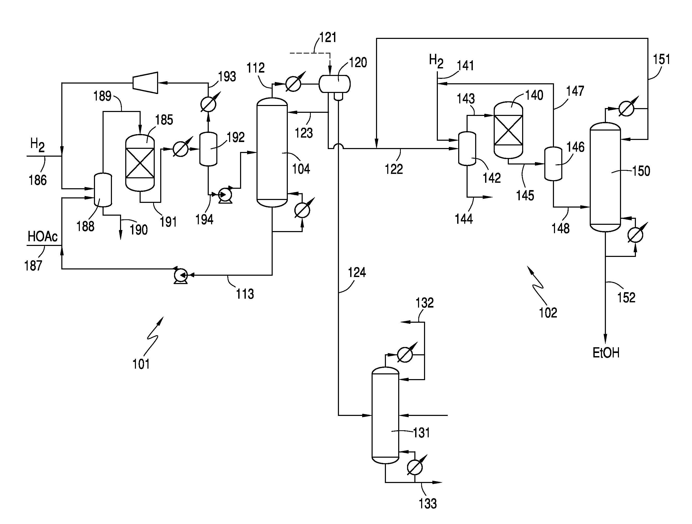
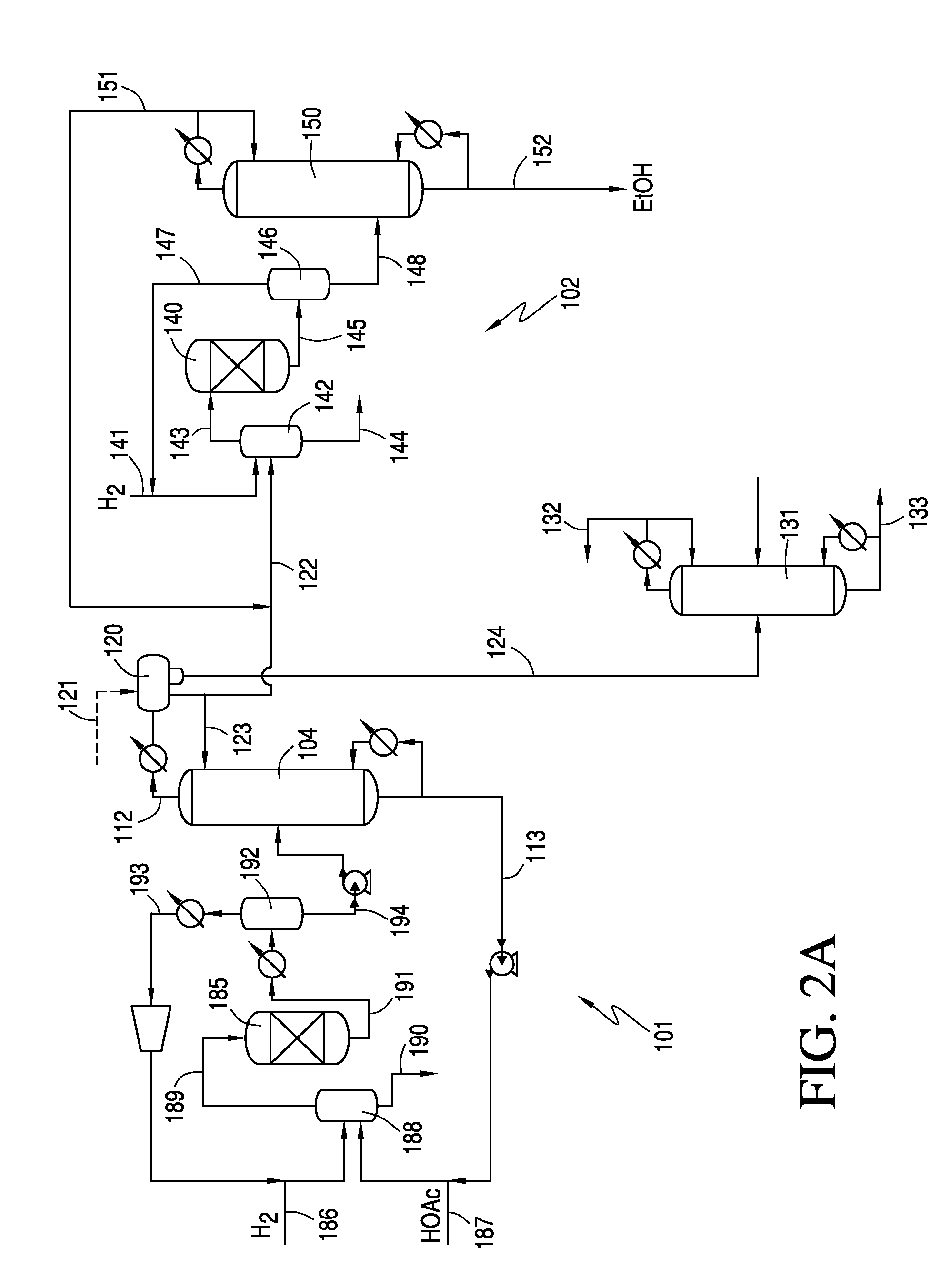
The patent is about a method of making ethanol by hydrogenating acetic acid and then reacting it with hydrogen to produce ethanol, diethyl acetal, and other alcohols. These are then separated using distillation columns to create a pure ethanol product with less diethyl acetal and alcohols with at least 4 carbon atoms. The technical effect of this invention is to provide a more efficient way to produce high-quality ethanol.

Problems solved by technology

In addition, none of the ethanol formed by reducing the ester feed stream is recycled to the first reactor.

Method used


Image

  • Hydrogenating Acetic Acid to Produce Ethyl Acetate and Reducing Ethyl Acetate to Ethanol
  • Hydrogenating Acetic Acid to Produce Ethyl Acetate and Reducing Ethyl Acetate to Ethanol
  • Hydrogenating Acetic Acid to Produce Ethyl Acetate and Reducing Ethyl Acetate to Ethanol

Examples


example a

Preparation of 1 Weight Percent Platinum and 5 Weight Percent Copper on High Purity Low Surface Area Silica

[0223]Powdered and meshed high purity low surface area silica (94 g) of uniform particle size distribution of about 0.2 mm was dried at 120° C. in an oven under nitrogen atmosphere overnight and then cooled to room temperature. To this was added a solution of platinum nitrate (Chempur) (1.64 g) in distilled water (16 ml). The resulting slurry was dried in an oven gradually heated to 110° C. (>2 hours, 10° C. / min). The impregnated catalyst mixture was then calcined at 500° C. (6 hours, 1° C. / min). To this calcined and cooled material was added a solution of copper nitrate trihydrate (Alfa Aesar) (19 g) in distilled water (19 ml). The resulting slurry was dried in an oven gradually heated to 110° C. (>2 hours, 10° C. / min). The impregnated catalyst mixture was then calcined at 500° C. (6 hours, 1° C. / min).

example b

Preparation of 1 Weight Percent Palladium and 5 Weight Percent Cobalt on High Purity Low Surface Area Silica

[0224]Powdered and meshed high purity low surface area silica (94 g) of uniform particle size distribution of about 0.2 mm was dried at 120° C. in an oven under nitrogen atmosphere overnight and then cooled to room temperature. To this was added a solution of palladium nitrate (Heraeus) (2.17 g) in distilled water (22 ml). The resulting slurry was dried in an oven gradually heated to 110° C. (>2 hours, 10° C. / min). The impregnated catalyst mixture was then calcined at 500° C. (6 hours, 1° C. / min). To this calcined and cooled material was added a solution of cobalt nitrate hexahydrate (24.7 g) in distilled water (25 ml). The resulting slurry was dried in an oven gradually heated to 110° C. (>2 hours, 10° C. / min). The impregnated catalyst mixture was then calcined at 500° C. (6 hours, 1° C. / min).

example c

[0225]Preparation of 1 weight percent palladium and 5 weight percent cobalt on H-ZSM-5. The procedures of Example B were substantially repeated except for utilizing H-ZSM-5 as the catalyst support.


PUM

PropertyMeasurementUnit
Temperatureaaaaaaaaaa
Fractionaaaaaaaaaa

Abstract

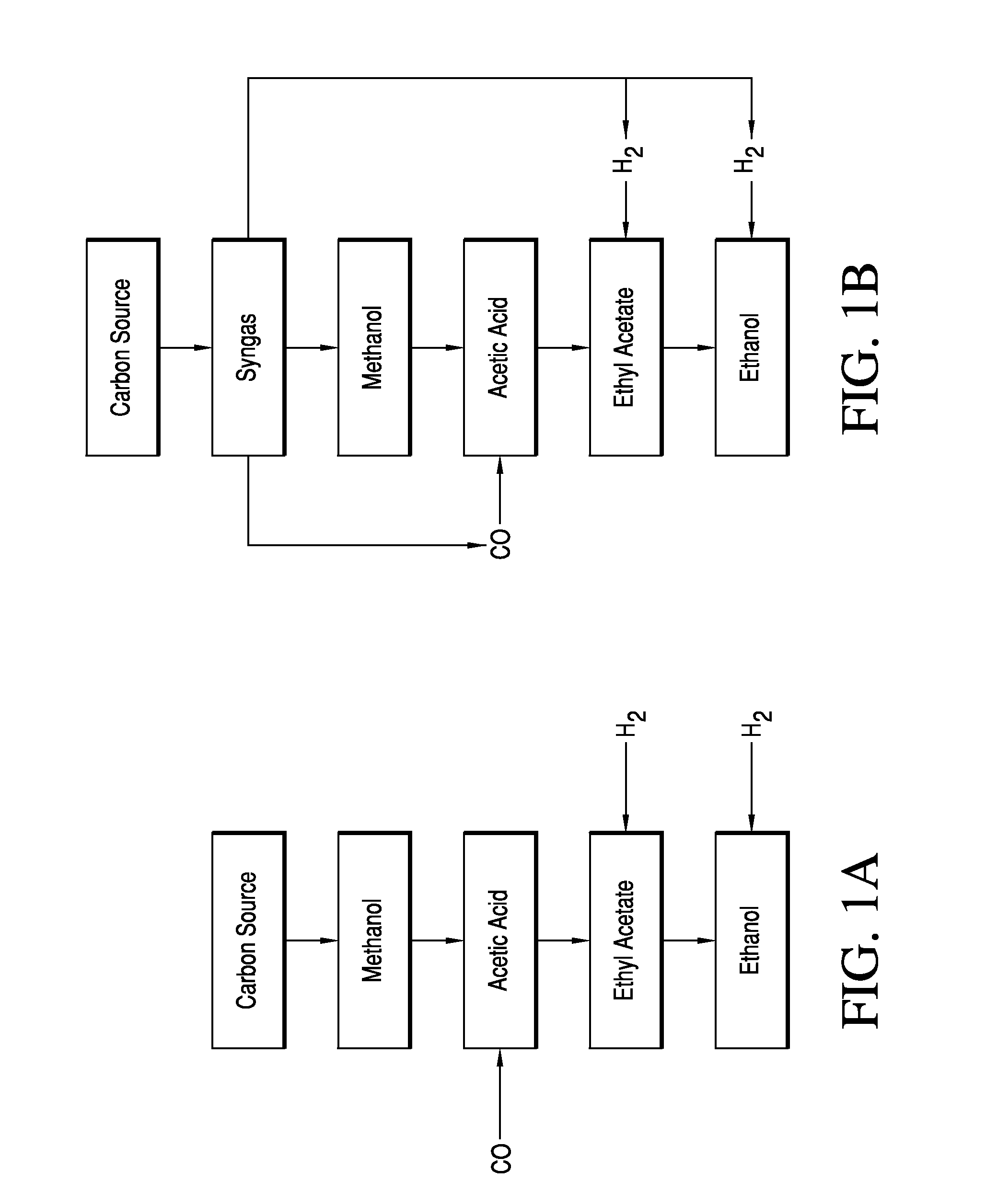
Disclosed herein are processes for alcohol production by reducing an ethyl acetate produced by hydrogenating acetic acid in the presence of a suitable catalyst. The ethyl acetate is reduced with hydrogen in the presence of a catalyst to obtain a crude reaction mixture comprising the alcohol, in particular ethanol, which may be separated from the crude reaction mixture. Thus, ethanol may be produced from acetic acid through an ethyl acetate intermediate without an esterification step. This may reduce the recycle of ethanol in the hydrogenolysis process and improve ethanol productivity.

Description

CROSS REFERENCE TO RELATED APPLICATIONS[0001]This application claims priority to U.S. Provisional App. No. 61 / 562,859, filed Nov. 22, 2011, the entirety of which is incorporated herein by reference.FIELD OF THE INVENTION[0002]The present invention relates generally to alcohol production from an acetic acid hydrogenation to form ethyl acetate, and in particular to producing ethanol by reducing ethyl acetate.BACKGROUND OF THE INVENTION[0003]Ethanol for industrial use is conventionally produced from petrochemical feed stocks, such as oil, natural gas, or coal, from feed stock intermediates, such as syngas, or from starchy materials or cellulose materials, such as corn or sugar cane. Conventional methods for producing ethanol from petrochemical feed stocks, as well as from cellulose materials, include the acid-catalyzed hydration of ethylene, methanol homologation, direct alcohol synthesis, and Fischer-Tropsch synthesis. Instability in petrochemical feed stock prices contributes to fluc...

Claims


Application Information

Patent Timeline
IPC IPC(8): C07C29/149
CPCC07C29/149C07C67/00C07C31/08C07C69/14
Inventor DUFF, EMILYFRANJKIC, IVAJOHNSTON, VICTOR J.LEE, DAVIDWARNER, R. JAYWEINER, HEIKOWOLLRAB, RADMILAZHOU, ZHENHUA
Owner CELANESE INT CORP
Learn More