
Dye-sensitized solar cell module and method of manufacturing the same

Active Publication Date: 2013-05-30
HYUNDAI MOTOR CO LTD
View PDF8 Cites 1 Cited by
  • Summary
  • Abstract
  • Description
  • Claims
  • Application Information

AI Technical Summary

Benefits of technology

The present invention provides a dye-sensitized solar cell module and a method of manufacturing the same, which improves the performance and efficiency of the module and panel through increasing the effective cell area. Furthermore, the module is designed to prevent damage to the electrodes and improve safety and quality. In addition, the electrolyte injection port is formed at an improved position to improve the overall safety and quality of the module. The connection parts formed at side surfaces of the modules make it easy to construct a panel and bond the modules.

Problems solved by technology

Among these types solar cells, silicon solar cells have already been widely used commercially in various fields such as houses and industrial plants, but their price and installation costs are prohibitively expensive for use on products such as vehicles and machinery.
However, it is impossible to apply the same frame structure as one would for a house to a structure, such as a sunroof or a panorama roof of a vehicle.
However, in the case of bonding two electrodes while preventing the two electrodes from completely overlapping on each other as described above, the exposed portions of the electrodes are fragile and impose restrictions on the design, so as to degrade the marketability.
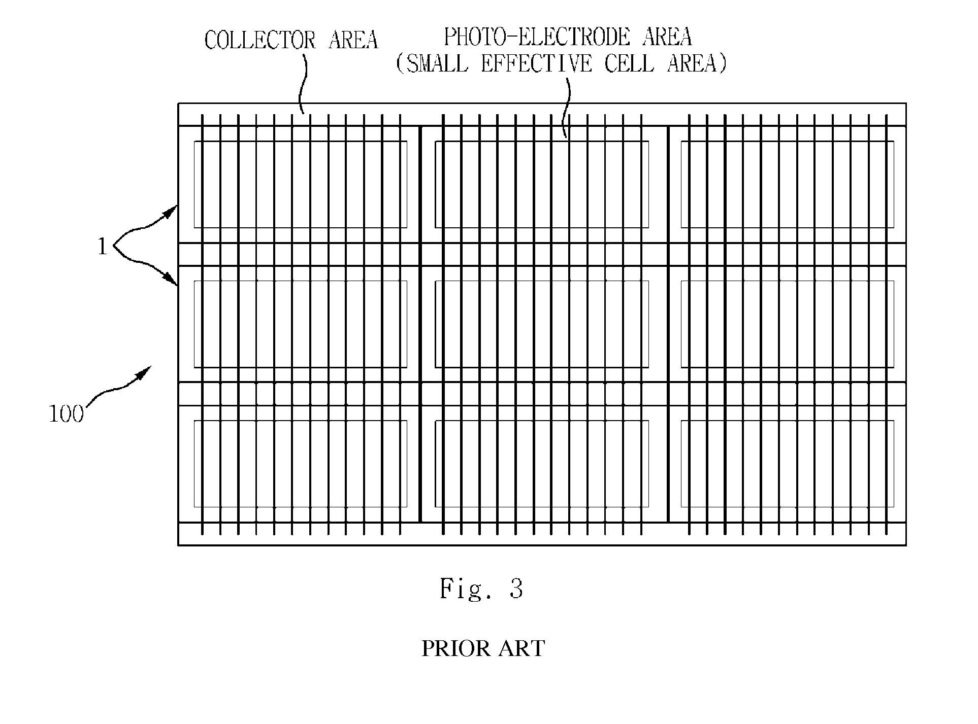
Due to the restrictions imposed by the exposed electrode area on the effective cell area, such as the area of photo-electrodes within the entire panel area, there limitations related to increasing the panel performance and efficiency.
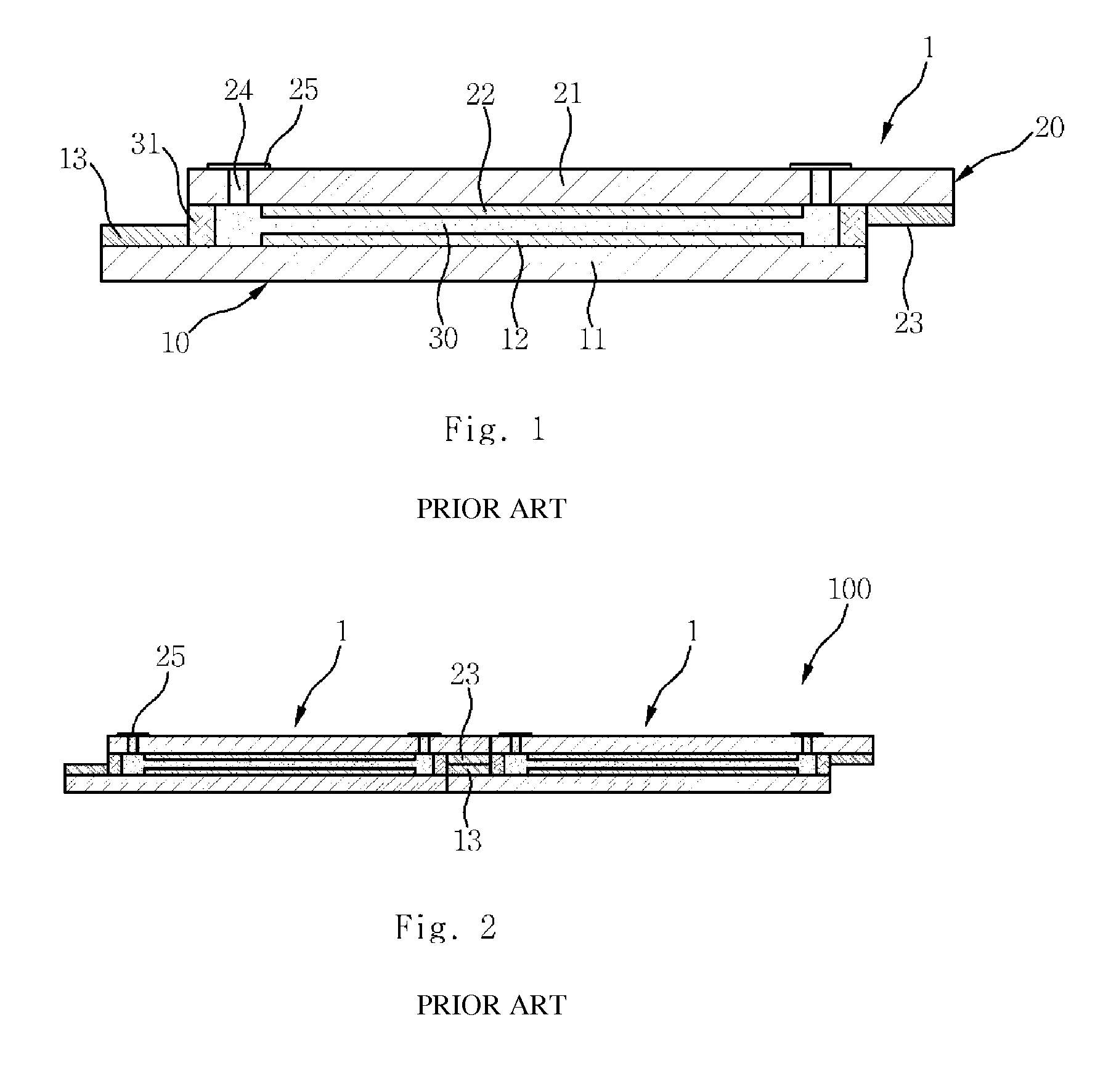
In blocking the electrolyte injection port 24, it is necessary to use a sealing glass 25 and an adhesive agent, such as surlyn, which increases the manufacturing cost.
As a result, the conventional structure has safety problems associated with its design, such as electrolyte leakage, and the sealing glass 25 attached over the electrolyte injection port 24 on the outer surface of the counter electrode 20 may degrade the outer appearance, so as to degrade the performance and marketability of the system.

Method used


Image

  • Dye-sensitized solar cell module and method of manufacturing the same
  • Dye-sensitized solar cell module and method of manufacturing the same
  • Dye-sensitized solar cell module and method of manufacturing the same

Examples


Embodiment Construction

[0043]Hereinafter, exemplary embodiments of the present invention will be described in detail with reference to the accompanying drawings so that those skilled in the art to which the invention pertains can easily carry out the present invention.

[0044]It is understood that the term “vehicle” or “vehicular” or other similar term as used herein is inclusive of motor vehicles in general such as passenger automobiles including sports utility vehicles (SUV), buses, trucks, various commercial vehicles, watercraft including a variety of boats and ships, aircraft, and the like, and includes hybrid vehicles, electric vehicles, combustion, plug-in hybrid electric vehicles, hydrogen-powered vehicles and other alternative fuel vehicles (e.g., fuels derived from resources other than petroleum).

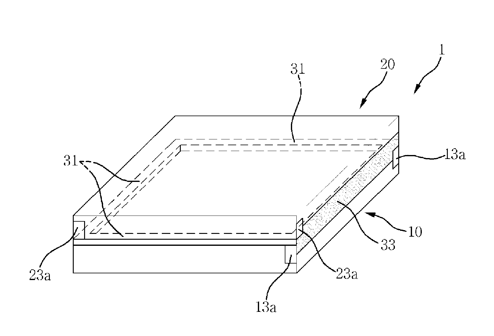
[0045]FIG. 4 is a cross-sectional view illustrating a dye-sensitized solar cell module according to an exemplary embodiment of the present invention, and FIG. 5 is a perspective view illustrating a dye-sen...


PUM


Abstract

Disclosed is a dye-sensitized solar cell module and a method of manufacturing the same. More specifically a counter electrode has connection parts formed within the side surfaces of the transparent conductive substrates. Edges of the working electrode and the counter electrode are bonded with each other by a sealant along the outer peripheral except for at one or more portions of the edges to form an electrolyte injection port. An electrolyte is then injected through the electrolyte injection hole into a space between the working electrode and the counter electrode. The electrolyte injection hole is then sealed by a sealant.

Description

CROSS-REFERENCE TO RELATED APPLICATION[0001]This application claims under 35 U.S.C. §119(a) the benefit of Korean Patent Application No. 10-2011-0126565 filed on Nov. 30, 2011, the entire contents of which are incorporated herein by reference.BACKGROUND[0002](a) Technical Field[0003]The present invention relates to a dye-sensitized solar cell module and a method of manufacturing the same. More particularly, the present invention relates to a dye-sensitized solar cell module, which improves the panel performance and efficiency by increasing the effective cell area, such as the area of photo-electrodes, with respect to the panel area in a constructed panel in comparison with the prior art, and a method of manufacturing the same.[0004](b) Background Art[0005]In recent years, as global warming is becoming a serious problem, technologies for utilizing environmentally friendly energies have begun emerging. Among them, the most environmentally friendly field is the solar cell field which u...

Claims


Application Information

Patent Timeline
IPC IPC(8): H01L31/048H01L31/18H01L31/0203
CPCH01G9/2031Y02E10/542H01G9/2077H01G9/2059Y02P70/50H01L31/042H01L31/0224H01L31/18H01G9/2081
Inventor SONG, MI YEONKIM, WON JUNGLEE, KI CHUNKIM, SANG HAKLEE, JI YONGJANG, YONG JUNKIM, YONG-GUSONG, IN WOO
Owner HYUNDAI MOTOR CO LTD
Learn More