Glass Pattern and Method for Forming the Same, Sealed Body and Method for Manufacturing the Same, and Light-Emitting Device

a glass pattern and pattern technology, applied in the field of sealed body and method for manufacturing the same, can solve the problems of inability to bake at high temperature in some cases, inability to increase scanning speed, and inability to achieve good increase beam intensity, reduce heat resistance, and improve product quality

Inactive Publication Date: 2013-05-30
SEMICON ENERGY LAB CO LTD
View PDF10 Cites 58 Cited by
  • Summary
  • Abstract
  • Description
  • Claims
  • Application Information

AI Technical Summary

Benefits of technology

[0035]According to the present invention, a glass pattern that can be used for a substrate provided with a material having low heat resistance and has increased productivity can be provided. Further, a sealed body having high hermeticity and increased productivity can be provided. Furthermore, a light-emitting device with high reliability including such a sealed body can be provided.

Problems solved by technology

On the other hand, a substrate to which a frit paste is applied cannot be baked at high temperature in some cases.
However, in order to remove the binder in the paste completely with the use of laser light, laser irradiation is needed for a certain period until the binder is vaporized and released; therefore, the scanning speed cannot be increased.
In the case of increasing the beam intensity of the laser light to remove the binder in a short period, when the beam intensity is too high, a sudden temperature change causes a crack in the substrate; therefore, the beam intensity cannot be well increased.
Consequently, in the case of using such a process of baking a frit paste by scanning with laser light, there is a problem in that the productivity cannot be increased.
At the time of overlapping a substrate provided with a glass pattern with a counter substrate, when a glass layer included in the glass pattern has a non-uniform thickness, a space is formed between the glass layer and the counter substrate which are welded to each other, resulting in a decrease in the hermeticity.
In the case of applying a frit paste along the periphery of a substrate, however, it has been difficult to apply the frit paste to have a uniform thickness by a coating method such as a dispensing method, for example.
The frit paste can be applied to have a substantially uniform thickness by a printing method such as a screen printing method; however, there have been problems in that an expensive printing plate needs to be used, and the printing method cannot be used particularly for a large-sized substrate.

Method used


Image

  • Glass Pattern and Method for Forming the Same, Sealed Body and Method for Manufacturing the Same, and Light-Emitting Device
  • Glass Pattern and Method for Forming the Same, Sealed Body and Method for Manufacturing the Same, and Light-Emitting Device
  • Glass Pattern and Method for Forming the Same, Sealed Body and Method for Manufacturing the Same, and Light-Emitting Device

Examples


embodiment 1

[0050]In this embodiment, a method for forming a glass pattern of one embodiment of the present invention and a method for manufacturing a sealed body of one embodiment of the present invention will be described with reference to drawings.

[Example of Manufacturing Process]

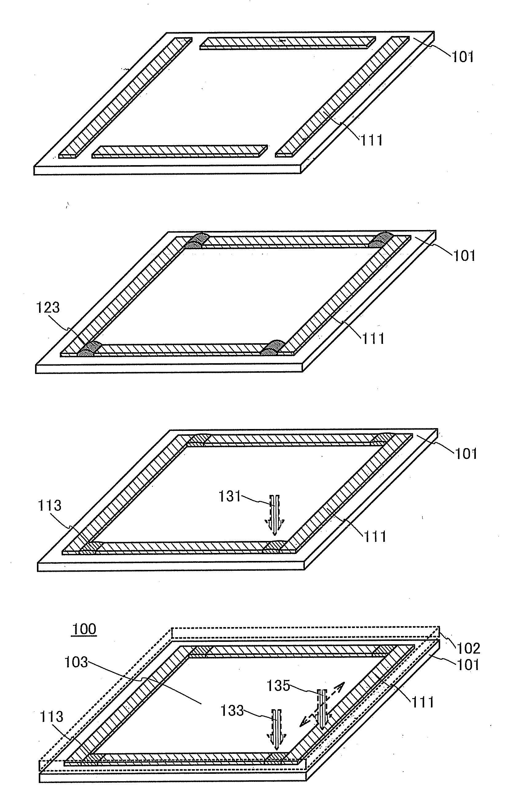
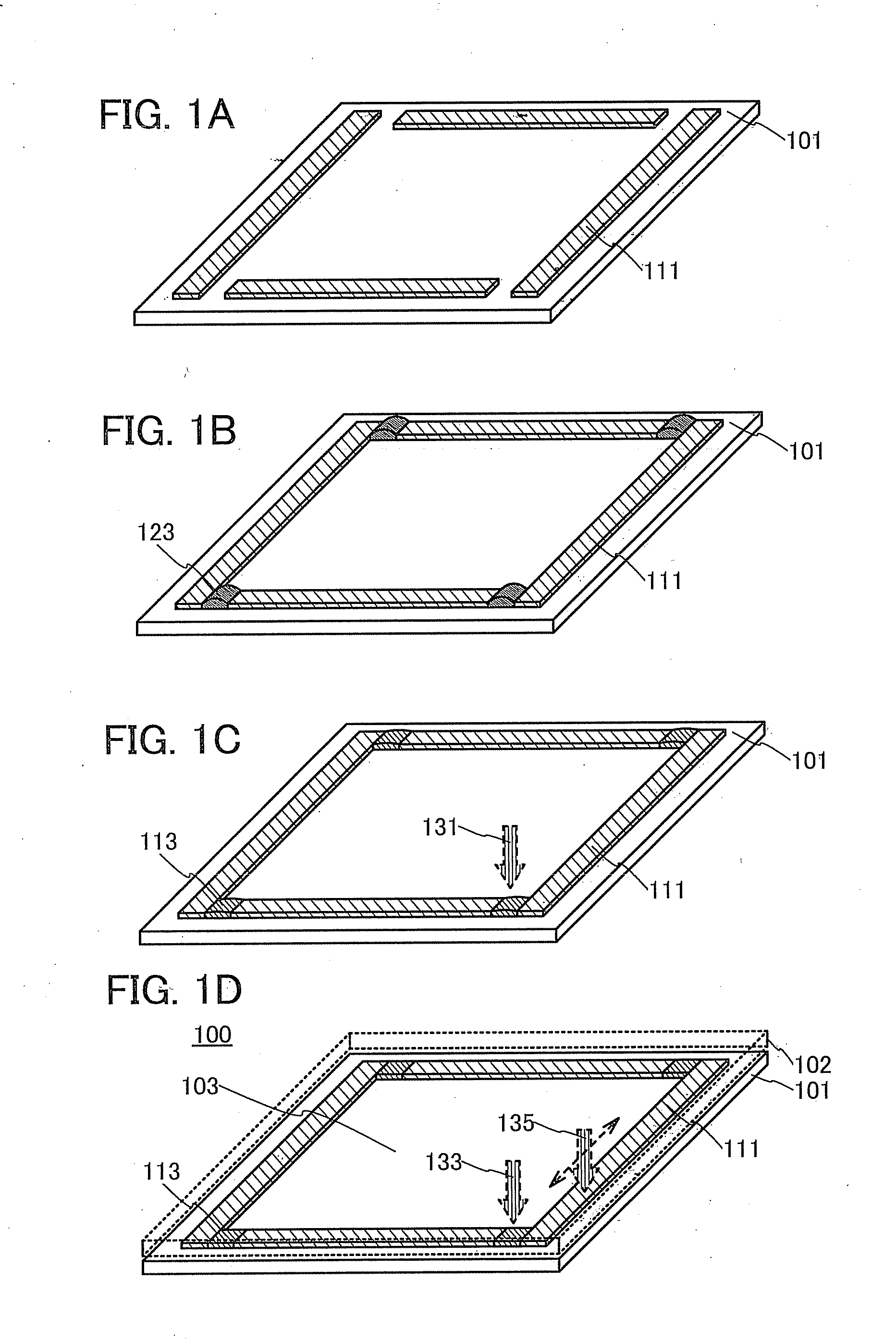
[0051]FIGS. 1A to 1D are schematic views showing an example of steps in the method for forming a glass pattern and the method for manufacturing a sealed body, which are described as examples in this embodiment.

[0052]First, a plurality of glass sheets 111 is arranged over a first substrate 101 (FIG, 1A).

[0053]The glass sheet 111 is a glass material which is a strip-like thin film. A glass sheet whose top surface and bottom surface have high flatness is preferably used as the glass sheet 111. A material, a structure, and the like which can be used for the glass sheet 111 will be described below in detail.

[0054]The glass sheets 111 are arranged over one surface of the first substrate 101 to surround a sealed region 10...

application example

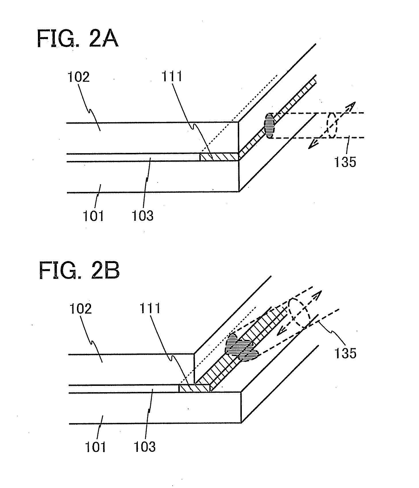
[0090]In the sealed body 100 of one embodiment of the present invention, the glass layer 113 formed of the glass frit is used in part of a sealing portion. Here, even in the case where there is a step under the frit paste 123 before the binder is removed, the step can be sufficiently covered with the frit paste 123. Further, immediately after the binder is removed, part of the glass frit is welded and thus the glass layer 113 can be porous; therefore, even a step is formed on a surface of the second substrate 102 in contact with the glass layer 113 from above, the step can be covered with the glass frit melted by irradiation of the laser light 135 performed later. For this reason, even when a step is formed in regions of the first substrate 101 and the second substrate 102 overlapping with the sealing portion, the step can be effectively filled with the use of the glass layer 113; therefore, high hermeticity can be maintained.

[0091]Here, in the case where a unit or the like is encap...

embodiment 2

[0138]In this embodiment, an example of a light-emitting device including a sealed body of one embodiment of the present invention will be described with reference to drawings.

[0139]The sealed body of one embodiment of the present invention has very high hermeticity, and thus can be used in various devices including an element such as an organic EL element, an organic semiconductor element, or an organic solar cell, whose performance is rapidly decreased once the element is exposed to the air (including moisture or oxygen). In addition, the method for manufacturing a sealed body, which is one embodiment of the present invention, can be used for a device including an element with low heat resistance, and thus various devices can be manufactured with high productivity.

[0140]As a light-emitting device including an organic EL element, a display device, a lighting device, or the like can be given. As a display device including an organic EL element, a display device employing a passive m...


PUM

PropertyMeasurementUnit
temperatureaaaaaaaaaa
thicknessaaaaaaaaaa
widthaaaaaaaaaa

Abstract

A glass pattern that can be used for a substrate provided with a material having low heat resistance and has increased productivity is provided. Further, a sealed body having high hermeticity and increased productivity is provided. Furthermore, a light-emitting device with high reliability including such a sealed body is provided. A glass sheet is used for a main portion of a glass pattern such as a straight line portion and a curved portion. In a joint portion of two glass sheets arranged in the corner portion, the straight line portion, or the like of the glass pattern, a frit paste is provided in contact with the glass sheets and is locally heated to remove the binder from the frit paste and to form a glass layer; thus, the glass sheets are fused to each other without any space provided therebetween.

Description

BACKGROUND OF THE INVENTION[0001]1. Field of the Invention[0002]The present invention relates to a sealed body and a method for manufacturing the sealed body. In addition, the present invention relates to a light-emitting device.[0003]2. Description of the Related Art[0004]A technique of forming a highly airtight sealed body by bonding two substrates to each other with glass (hereinafter also referred to as a glass layer) obtained by melting or sintering glass frit including low-melting glass has been known. In a technique disclosed in Patent Document 1, a paste containing a binder and glass frit including low-melting glass is applied to a glass substrate along an edge of the glass substrate, the binder is removed and the glass frit is melted to form a glass layer by baking of the paste, and the glass layer is irradiated with laser light with the substrate overlapping with a counter substrate so that the substrate and the counter substrate are bonded to each other with the glass lay...

Claims


Application Information

Patent Timeline
Patent Type & Authority Applications(United States)
IPC IPC(8): H01L51/50C03B23/203
CPCH01L51/5012C03B23/203Y10T428/197H01L51/5246Y10T428/1317C03B23/24Y02P40/57H10K50/8426H05B33/04H10K50/11
Inventor SHIMOMURA, AKIHISAYOSHIZUMI, KENSUKE
Owner SEMICON ENERGY LAB CO LTD
Why Eureka
Try Eureka