
Systems and methods for managing advanced metering infrastructure

Active Publication Date: 2013-06-06
FLORIDA POWER & LIGHT
View PDF16 Cites 24 Cited by
  • Summary
  • Abstract
  • Description
  • Claims
  • Application Information

AI Technical Summary

Benefits of technology

The patent text describes a system that helps manage and control a utility's network of meters. This system can collect data from the meters, improve energy efficiency, and accurately bill customers. It can also help detect and isolate outages in the network. Overall, this system can make the utility more efficient and effective at managing its network.

Problems solved by technology

Meter manufacturers were not able to use this raw metered data as a way to differentiate themselves from their competitors.
There are known drawbacks to that conventional metering approach, namely, increased functionality in the meter requires an increase in processing power and a commensurate increase in cost; the memory available “under the glass” in a meter is finite (i.e., in order to add an option one must remove another option or increase the memory); to upgrade or re-program a meter required a meter technician to drive to the meter location, physically remove the meter (or switch it out with a replacement meter) and then return it to the “meter shop” where the meter can be upgraded, and after the upgrade is complete, the meter was to be returned and re-installed; different meters require different interfaces and different communications protocols for retrieving data; increased application complexity in the firmware of the meter led to a higher probability of errors that may require upgrades; increased application functionality housed in the firmware of the meter typically requires complex configuration or programming of the end-device, which greatly increased the system management, coordination, and synchronization; and meter inventory must be increased in order to accommodate different configurations, functionalities, and versions of metering devices.
However, there are limitations associated with these methods of remote communications: wireless communication with the meter is often limited to off peak hours determined by the various network providers; satellite-based communications are limited to line of sight communication between the meter and the satellite, thus limiting the times when the meter may be contacted; wireless and orbital satellite networks are costly, often billing per byte of data transmitted, thus limiting the amount of data which can effectively be transmitted.
Existing AMR / AMI systems are also limited in that they require several layers of applications and interfaces in order to communicate with connected meters.
Industry standards intended to unify the communication and device protocols typically fall short by setting minimum requirements for compliance and / or providing manufacturer-specific mechanisms to allow variability and customizations.
The increasing variety of meters presents an almost insurmountable challenge to the automated meter reading industry.
Deregulation of the electricity metering industry has created even more challenges.
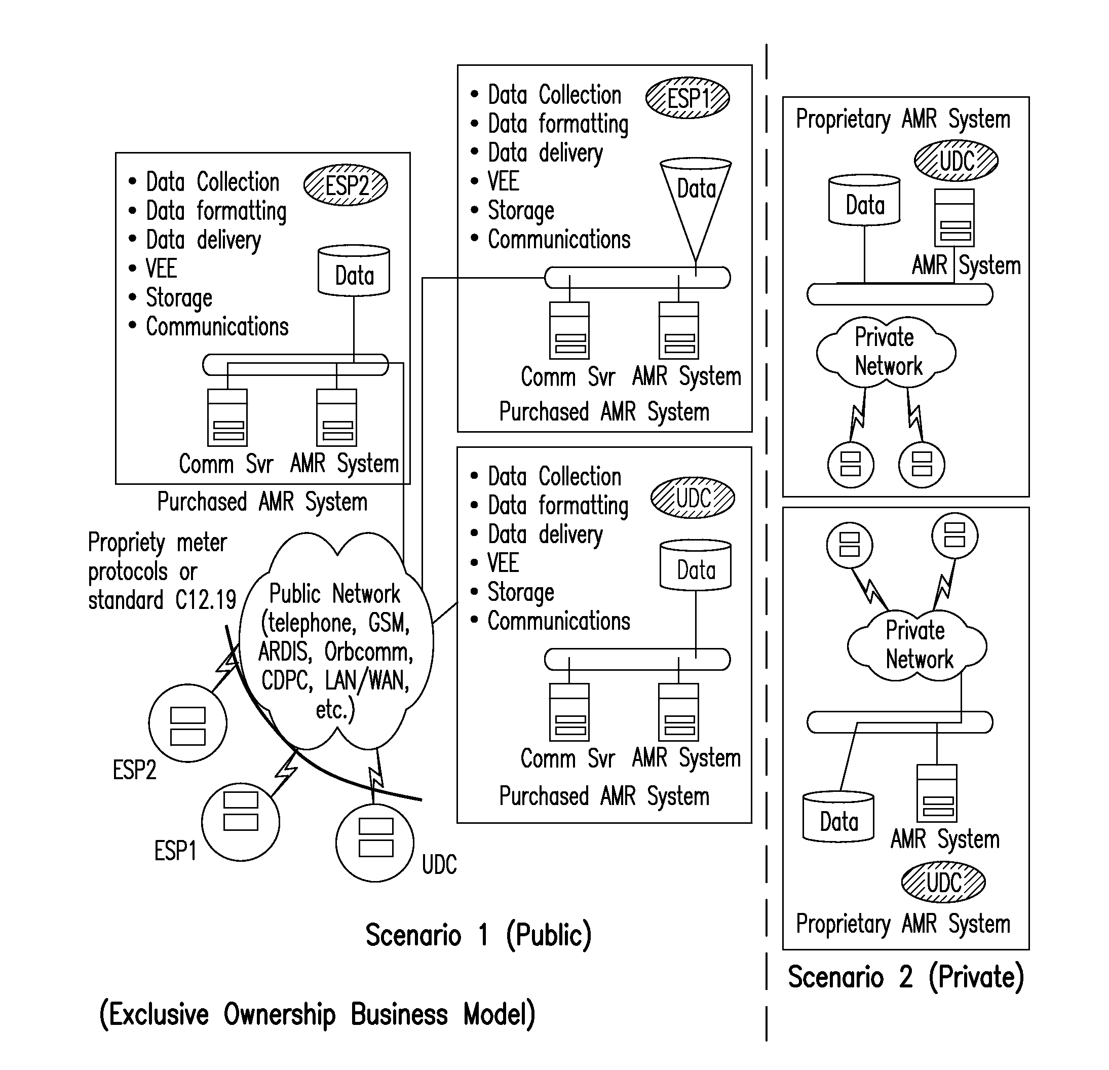
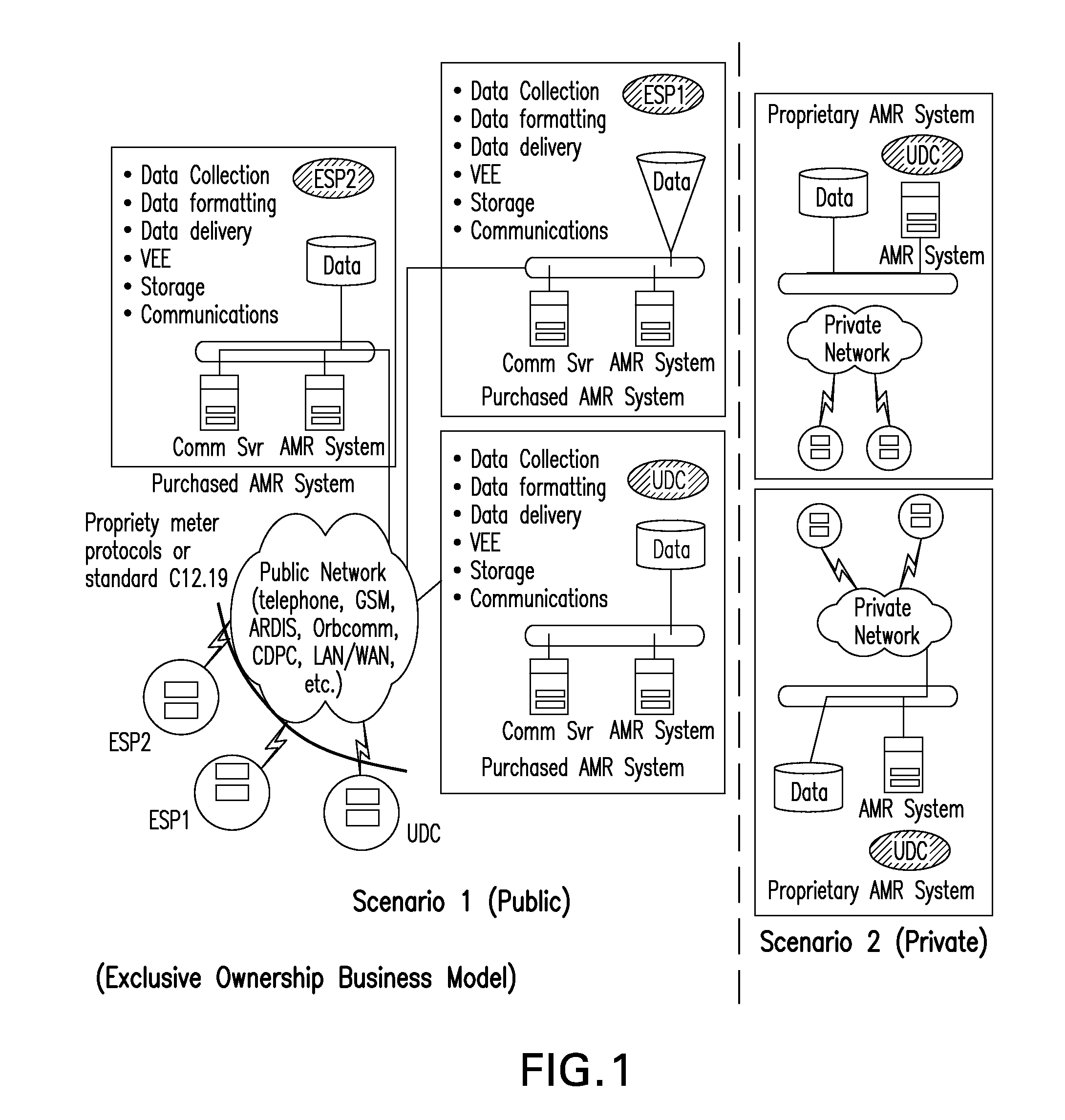
A key difference between the public and private type communication networks is that the private network requires additional up-front cost to deploy the infrastructure of the fixed network to blanket one or more service areas.
In the exclusive owner business model (FIG. 1), the meter data users (MDUs) (i.e., ESPs, UDCs, MDMAs, etc.) purchase an AMR / AMI system with a significant up-front cost.
Taken alone, the measurable benefits listed above typically may not justify the expense incurred by purchasing an AMR / AMI system.
Consequently, the number of large AMR System deployments has not reached expectations.
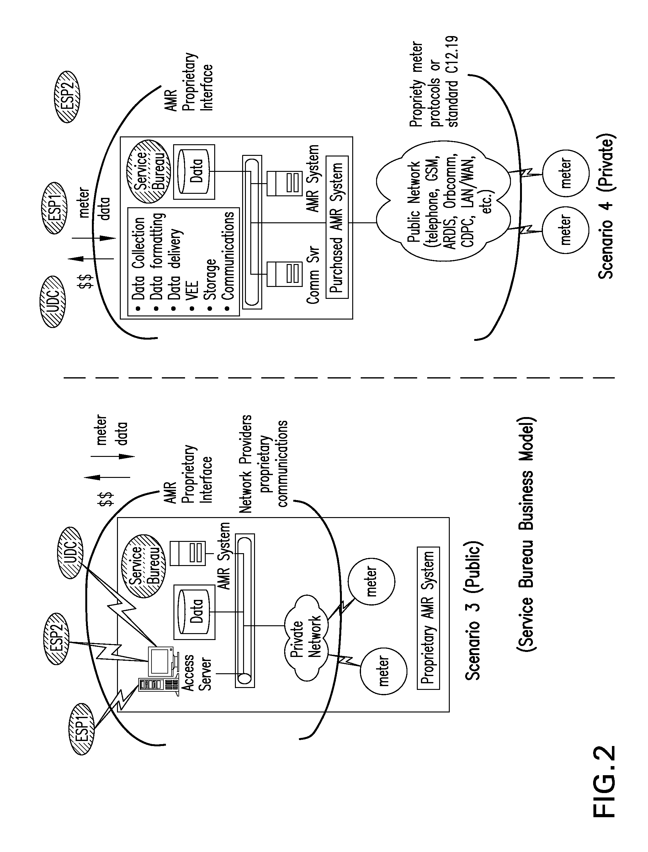
The service bureau model could create some conflicts, or perceived conflicts, when competing MDUs utilize the same service bureau for metered information.
However, one problem of implementing such system in-house is that once the MDMA system has been implemented in a particular manner, applying a set of open standards or an MDMA-specific set of configurations, it may become cost-prohibitive to move such application to the utility.

Method used


Image

  • Systems and methods for managing advanced metering infrastructure
  • Systems and methods for managing advanced metering infrastructure
  • Systems and methods for managing advanced metering infrastructure

Examples


Embodiment Construction

[0032]The following detailed description of certain embodiments of the subject matter set forth herein, will be better understood when read in conjunction with the appended drawings. As used herein, an element or step recited in the singular and proceeded with the word “a” or “an” should be understood as not excluding plural of said elements or steps, unless such exclusion is explicitly stated. In this document, the term “or” is used to refer to a nonexclusive or, unless otherwise indicated. Furthermore, references to “one embodiment” are not intended to be interpreted as excluding the existence of additional embodiments that also incorporate the recited features. Moreover, unless explicitly stated to the contrary, embodiments “comprising” or “having” an element or a plurality of elements having a particular property may include additional such elements not having that property.

[0033]In the following detailed description, reference is made to the accompanying drawings which form a p...


PUM


Abstract

A system for maintaining and hosting an AMI command and control application is disclosed. The system includes an AMI command and control application module in a network compartment for measuring energy usage from customer meters, managing an AMI network, and executing connect / disconnect orders; and a plurality of firewalls to provide a security perimeter to the AMI command and control application module when the module is accessed by a vendor network or a utility network. The AMI command and control application module includes a VPN concentrator and a 6 in 4 router to provide a security perimeter between the AMI command and control application module and the AMI network.

Description

BACKGROUND OF THE INVENTION[0001]Embodiments of the present invention generally relate to advanced metering infrastructure (AMI) used in electricity meters, gas meters, water meters and the like, and more particularly, the present invention relates to methods and systems related to an AMI command and control management application module and system.[0002]Electricity generated at a power station may be produced using a plurality of energy sources, such as coal powered power stations, nuclear fission, hydroelectric stations, wind farms, solar photovoltaic cells, etc. This power generated at the power station is transmitted to users over a transmission grid. In recent years advancements have been made in transmission of power to an end user. One such advancement has been in the area of electrical power meters.[0003]An electrical power meter may be implemented as an automatic meter reader (AMR) where the electricity usage is communicated one way to a meter reader. More recently, AMI has...

Claims


Application Information

Patent Timeline
IPC IPC(8): H04L29/06
CPCH04L63/0272
Inventor OLLUKAREN, PAUL J.SWAMINATHAN, RADHAKRISHNANKING, SUSAN LYNNMCBEE, KEITH WAYNEGUTIERREZ, JULIO C.RODRIGUEZ-PEREZ, MANUEL
Owner FLORIDA POWER & LIGHT
Learn More