Planar Plasmon Generator with a Scalable Feature for TAMR

a plasmon generator and feature technology, applied in combination recording, data recording, instruments, etc., can solve the problems of not meeting the requirements simultaneously, increasing the recording area density, and reducing so as to reduce the optical/thermal spot size, the effect of reducing the track width

Active Publication Date: 2013-06-13
HEADWAY TECH INC
View PDF3 Cites 39 Cited by
  • Summary
  • Abstract
  • Description
  • Claims
  • Application Information

AI Technical Summary

Benefits of technology

[0024]It is an object of this invention to produce a plasmon generating structure that has scalability and extendability in terms of reducing the optical / thermal spot size in the medium, therefore reducing track width and improving track density.
[0025]It is a further object of this invention to produce a plasmon generator structure that has the capability of improving the thermal gradient in the medium, thereby improving linear recording density.

Problems solved by technology

This latter effect is the thermal instability of the extremely small regions of magnetic material on which information must be recorded, in order to achieve the required data densities.
Satisfying these requirements simultaneously may be a limiting factor in the further development of the present magnetic recording scheme used in state of the art hard-disk-drives (HDD).
If that is the case, further increases in recording area density may not be achievable within those schemes.
Even with a 5 nm tip radius it is difficult to obtain an optical spot size that is less than 50 nm in the medium, which is a requirement for the first generation of TAMR products.
Neither of these results are desirable and they increase the concern over EPG reliability.
In addition, the level of process control required to produce such a sharp tip angle is itself challenging.

Method used


Image

  • Planar Plasmon Generator with a Scalable Feature for TAMR
  • Planar Plasmon Generator with a Scalable Feature for TAMR
  • Planar Plasmon Generator with a Scalable Feature for TAMR

Examples


first embodiment

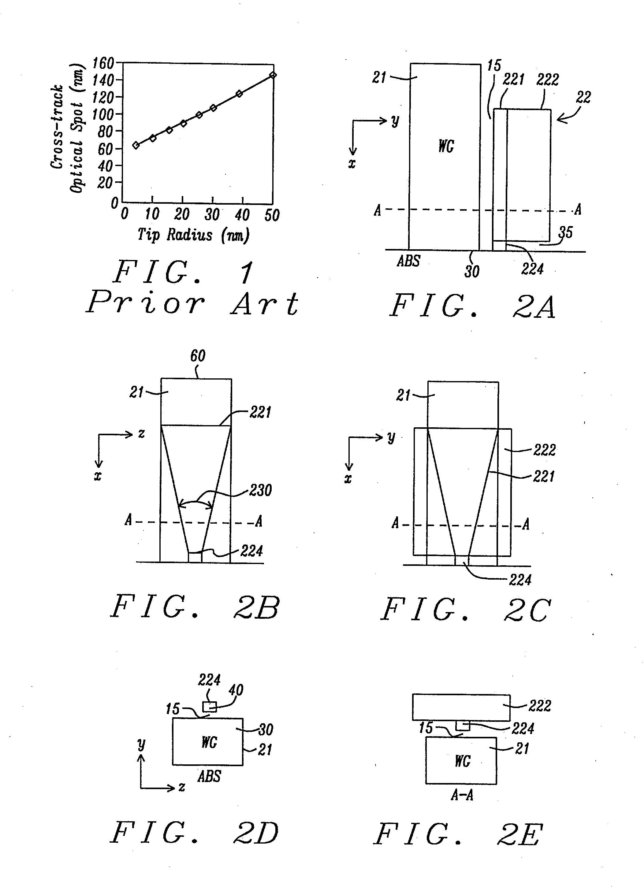
[0044]Referring first to FIG. 2A, there is shown a side cross-sectional view (in an x-y plane) of a portion of a first embodiment of a PPG for a TAMR apparatus that meets the objects of the present invention. Unlike the remaining six embodiments below, this first embodiment is the planar plasmon generator (PPG) itself and it does not include any particular configuration of the magnetic pole that is typically located adjacent to. The combination of the PPG and the adjacent magnetic pole comprises the TAMR head. These TAMR combinations will be described below as the second to seventh embodiments of the invention.

[0045]The y-axis hereinafter (in all subsequent embodiments) defines the down-track direction, the x-axis hereinafter defines a vertical direction (perpendicular to the ABS) from the back end of the head towards the ABS end, the z-axis would be a cross-track direction in the plane of the recording medium and is not shown in this figure. A line, A-A, indicates the plane along w...

second embodiment

[0059]Referring to schematic FIGS. 5A and 5B, there is shown a side (x-y plane) cross-sectional view (5A), and an ABS (y-z plane) cross-sectional view (5B) of a second embodiment of a TAMR write head incorporating a PPG and adjacent optical WG of the present invention. The arrow (1) points in the direction of medium movement relative to the head.

[0060]This embodiment shows a tri-layer planar Plasmon generator (22), abutting a magnetic write pole (23). The write pole has a small stitched pole tip (231) projecting in the negative y-direction towards the WG (21). Such a stitched pole tip is well known in the art and will not be discussed herein. The write pole (23) is substantially of uniform thickness above the stitched pole tip. The WG (21) is separated from the plasmon generator by a dielectric-filled gap or spacer layer (15). The main pole connects to a yoke which is not shown here.

[0061]The planar Plasmon generator (22) in this embodiment consists of three layers, layer 1 (221) cl...

third embodiment

[0065]Referring to schematic FIGS. 6A and 6B, there is shown a side (x-y plane) cross-sectional view (6A), and an ABS (y-z plane) cross-sectional view (6B) of a third embodiment of a TAMR write head incorporating a PPG and adjacent optical WG of the present invention.

[0066]In every other aspect, this embodiment is same as the second embodiment, except that two blocks ((241) and (242)), visible in 6B, are placed around the magnetic pole as additional heat sinks. The blocks can be made from non-corroding metals with good thermal conductivity, such as Ru, Cr, Au etc, or made from other hard materials with good thermal conductivity, such as SiC etc. This configuration will have the advantages of further lowering the temperature of magnetic pole during writing operation so reliability of the apparatus is improved.


PUM

PropertyMeasurementUnit
vertex angleaaaaaaaaaa
widthaaaaaaaaaa

Abstract

A TAMR (Thermal Assisted Magnetic Recording) write head uses the energy of optical-laser excited surface plasmons in a scalable planar plasmon generator to locally heat a magnetic recording medium and reduce its coercivity and magnetic anisotropy. The planar plasmon generator is formed as a multi-layered structure in which one planar layer supports a propagating surface plasmon mode that is excited by evanescent coupling to an optical mode in an adjacent waveguide. A peg, which can be a free-standing element or an integral projection from one of the layers, is positioned between the ABS end of the generator and the surface of the recording medium, confines and concentrates the near field of the plasmon mode immediately around and beneath it.

Description

BACKGROUND OF THE INVENTION[0001]1. Field of the Invention[0002]This invention relates to the fabrication of magnetic read / write heads that employ TAMR (thermally assisted magnetic recording) to enable writing on magnetic media having high coercivity and high magnetic anisotropy. More particularly, it relates to the use of a planar plasmon generator (PPG) to transfer the required thermal energy from the read / write head to the media by means of a propagating surface plasmon mode.[0003]2. Description of the Related Art[0004]Magnetic recording at area data densities of between 1 and 10 Tera-bits per in2 involves the development of new magnetic recording media, new magnetic recording heads and, most importantly, a new magnetic recording scheme that can delay the onset of the so-called “superparamagnetic” effect. This latter effect is the thermal instability of the extremely small regions of magnetic material on which information must be recorded, in order to achieve the required data de...

Claims


Application Information

Patent Timeline
Patent Type & Authority Applications(United States)
IPC IPC(8): G11B13/04G11B7/1387
CPCG11B5/314G11B2005/0021G11B5/6088
Inventor JIN, XUHUIMALETZKY, TOBIASSONG, SUPINGZHOU, DAYUSMYTH, JOEDOVEK, MORIS
Owner HEADWAY TECH INC
Why Eureka
Try Eureka