Energy storage device, system with energy storage device and method for driving an energy storage device

a technology of energy storage cell and energy storage module, which is applied in the direction of battery/fuel cell control arrangement, transportation and packaging, dc network circuit arrangement, etc., can solve the problems of power reduction in the entire energy supply line, failure of the entire system, so as to reduce the weight of the system, increase the utilization of existing energy storage cell modules, and reduce the amount of installation space

Active Publication Date: 2013-06-20
ROBERT BOSCH GMBH
View PDF2 Cites 13 Cited by
  • Summary
  • Abstract
  • Description
  • Claims
  • Application Information

AI Technical Summary

Benefits of technology

[0014]A considerable advantage associated with this arrangement consists in that the energy storage device can be used in a system for which an additional voltage level is required, without any additional implementation measures. For example, when using the energy storage device in an electrically operated vehicle, a supply voltage for the electric drive and a high-voltage DC voltage for the high-voltage on-board electrical system of the electrically operated vehicle can be generated simultaneously.
[0015]Advantageously, owing to the parallel use of energy storage modules for the provision of one of two voltage levels, the degree of utilization of the

Problems solved by technology

The series circuit comprising a plurality of battery modules is associated with the problem that the entire line fails when a single battery module fails.
Such a failure of the energy supply line can r

Method used


Image

  • Energy storage device, system with energy storage device and method for driving an energy storage device
  • Energy storage device, system with energy storage device and method for driving an energy storage device
  • Energy storage device, system with energy storage device and method for driving an energy storage device

Examples


Embodiment Construction

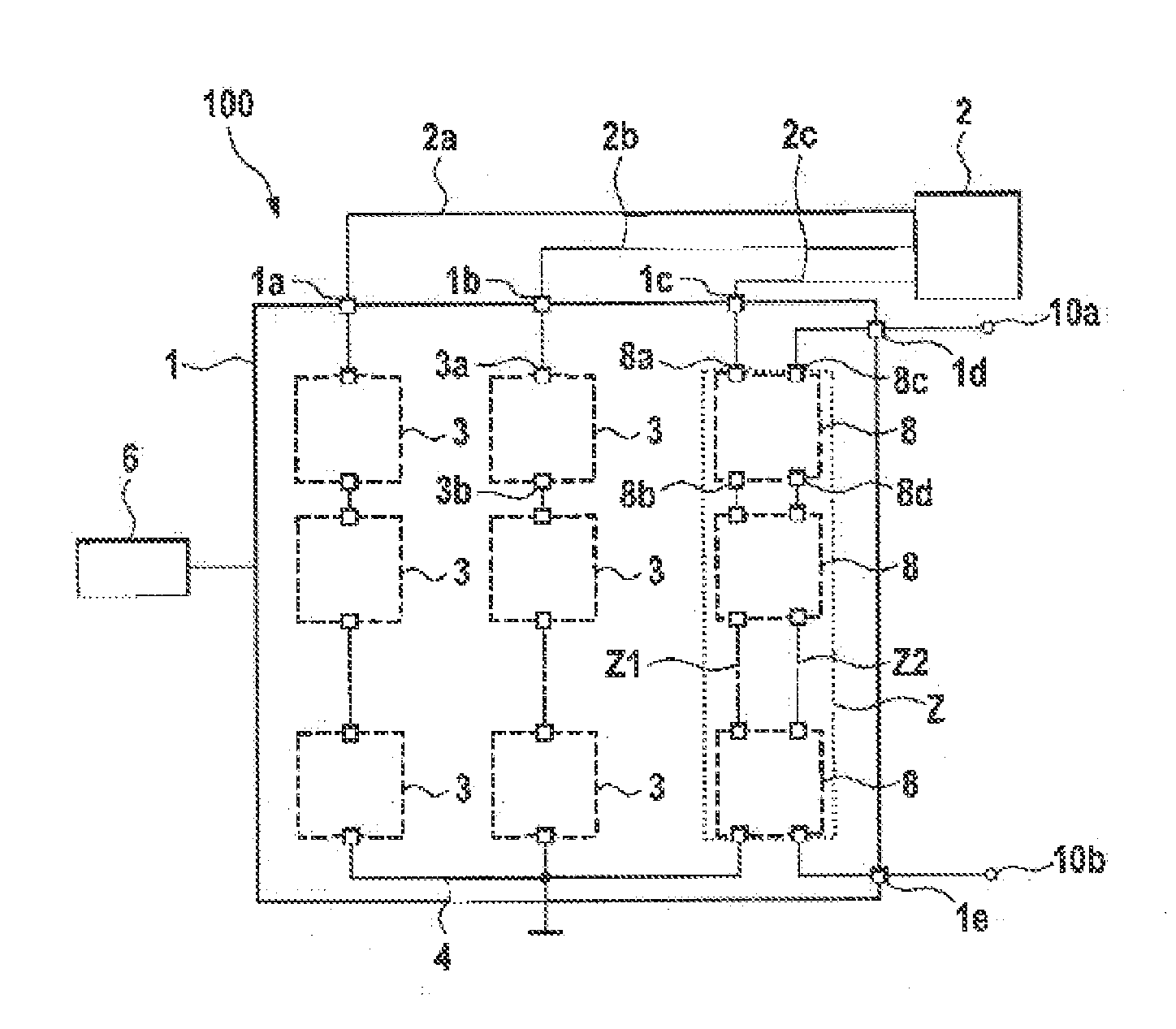
[0031]FIG. 1 shows a schematic illustration of a system 100 having an energy storage device 1 for voltage conversion of DC voltage provided by energy storage modules 3 and 8 into an n-phase AC voltage, on the one hand, and a DC voltage, on the other hand. The energy storage device 1 comprises a large number of energy supply branches, of which three are shown by way of example in FIG. 1, which are suitable for generating a three-phase AC voltage, for example for a three-phase machine 2. However, it is clear that any other number of energy supply branches can likewise be possible. Some of the energy supply branches can have a large number of energy storage modules 3, which are connected in series in energy supply branches. By way of example, in each case three energy storage modules 3 per energy supply branch are shown in FIG. 1, but any other number of energy storage modules 3 can likewise be possible. At each of the energy supply branches, the energy storage device 1 has an output c...


PUM


Abstract

An energy storage device. An energy supply branch, with a plurality of energy storage modules is connected in series via first module connections along a first energy supply line and via second module connections along a second energy supply line. The energy storage modules include an energy storage cell module having an energy storage cell, a first coupling device having first coupling elements, configured to switch or bypass the energy storage cell module selectively between the first module connections, and a second coupling device having second coupling elements, which are designed to switch or bypass the energy storage cell module selectively between the second module connections. The energy storage device also includes an output connection coupled to an output of the first energy supply line; and two additional connections coupled to the outputs of the second energy supply line.

Description

BACKGROUND OF THE INVENTION[0001]The invention relates to an energy storage device, a system having an energy storage device and a method for driving an energy storage device, in particular in a battery direct converter circuit for simultaneous power supply to an electric machine and generation of a further voltage level for a DC voltage system.[0002]The trend is that in the future electronic systems which combine new energy storage technologies with electrical drive technology will be used increasingly both in stationary applications, such as wind power installations or solar installations, and in vehicles, such as hybrid or electric vehicles.[0003]The feed of polyphase current to an electric machine is generally provided by a converter in the form of a pulse-controlled inverter. For this purpose, a DC voltage provided by a DC voltage intermediate circuit can be converted into a polyphase AC voltage, for example a three-phase AC voltage. The DC voltage intermediate circuit is in th...

Claims


Application Information

Patent Timeline
IPC IPC(8): H02J1/00
CPCB60L11/1853B60L11/1864Y02T10/7061Y02T10/7005H02J1/00B60L58/18B60L58/21Y02T10/70
Inventor TIEFENBACH, ANDY
Owner ROBERT BOSCH GMBH
Why Eureka
Try Eureka