Battery with a recyclable dry particle based electrode

a dry particle and electrode technology, applied in the direction of non-metal conductors, cell components, conductors, etc., can solve the problems of undesirable destructive breakdown, undesirable destructive breakdown of double-layer capacitors, and no operating voltage of double-layer capacitors, etc., to achieve high yield, high reliability, and low cost.

Inactive Publication Date: 2013-06-20
TESLA INC
View PDF2 Cites 48 Cited by
  • Summary
  • Abstract
  • Description
  • Claims
  • Application Information

AI Technical Summary

Benefits of technology

[0016]The present invention provides a high yield method for making inexpensive, durable, an...

Problems solved by technology

Overall cost of a device is an important characteristic that can make or break a decision as to whether a particular type of device is used.
Although, double-layer capacitors can theoretically be operated at voltages as high as 4.0 volts and possibly higher, current double-layer capacitor manufacturing technologies limit nominal operating voltages of double-layer capacitors to about 2.5 to 2.7 volts.
Higher operating voltages are possible, but at such voltages undesirable destructive breakdown begins to occur, which in part may be due to interactions with impurities and residues that can be introduced into, or attach themselves to, electrodes during manufacture.
For example, undesirable destructive breakdown of double-layer capacitors is seen to appear at voltages between about 2.7 to 3.0 volts.
When such additives are utilized in the manufacture of a capacitor product, the operating lifetime, as well maximum operating voltage, of a final capacitor product may become reduced, typically because of undesirable chemical interactions that can occur between residues of the additive(s) and a subsequently used capacitor electrolyte.
With prior art coating based processes, as layer thickness is increased above a certain thickness or decreased...

Method used


Image

  • Battery with a recyclable dry particle based electrode
  • Battery with a recyclable dry particle based electrode
  • Battery with a recyclable dry particle based electrode

Examples


Embodiment Construction

[0068]Reference will now be made in detail to embodiments of the invention that are illustrated in the accompanying drawings. Wherever possible, same or similar reference numerals are used to refer to same or similar steps and / or elements used therein.

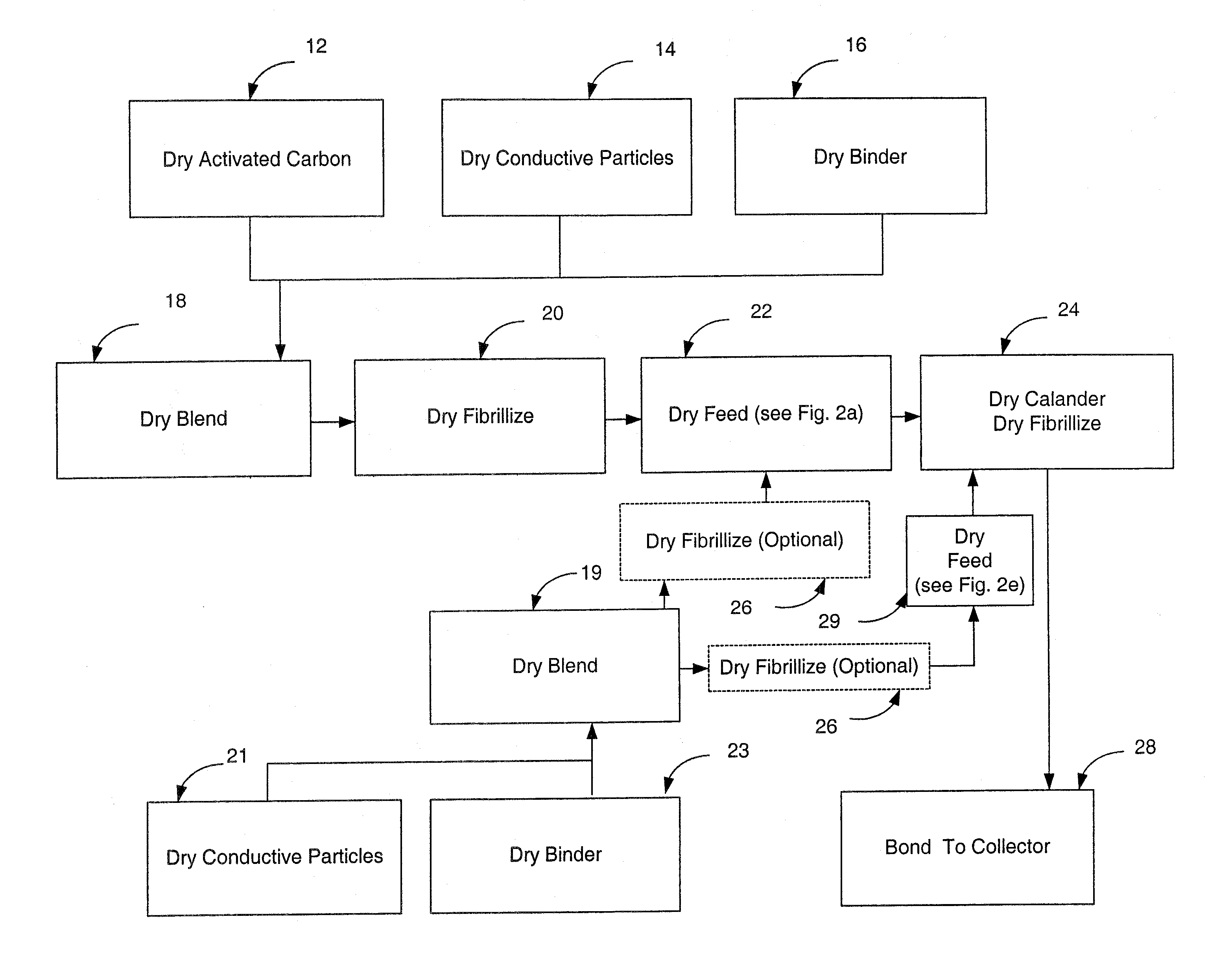
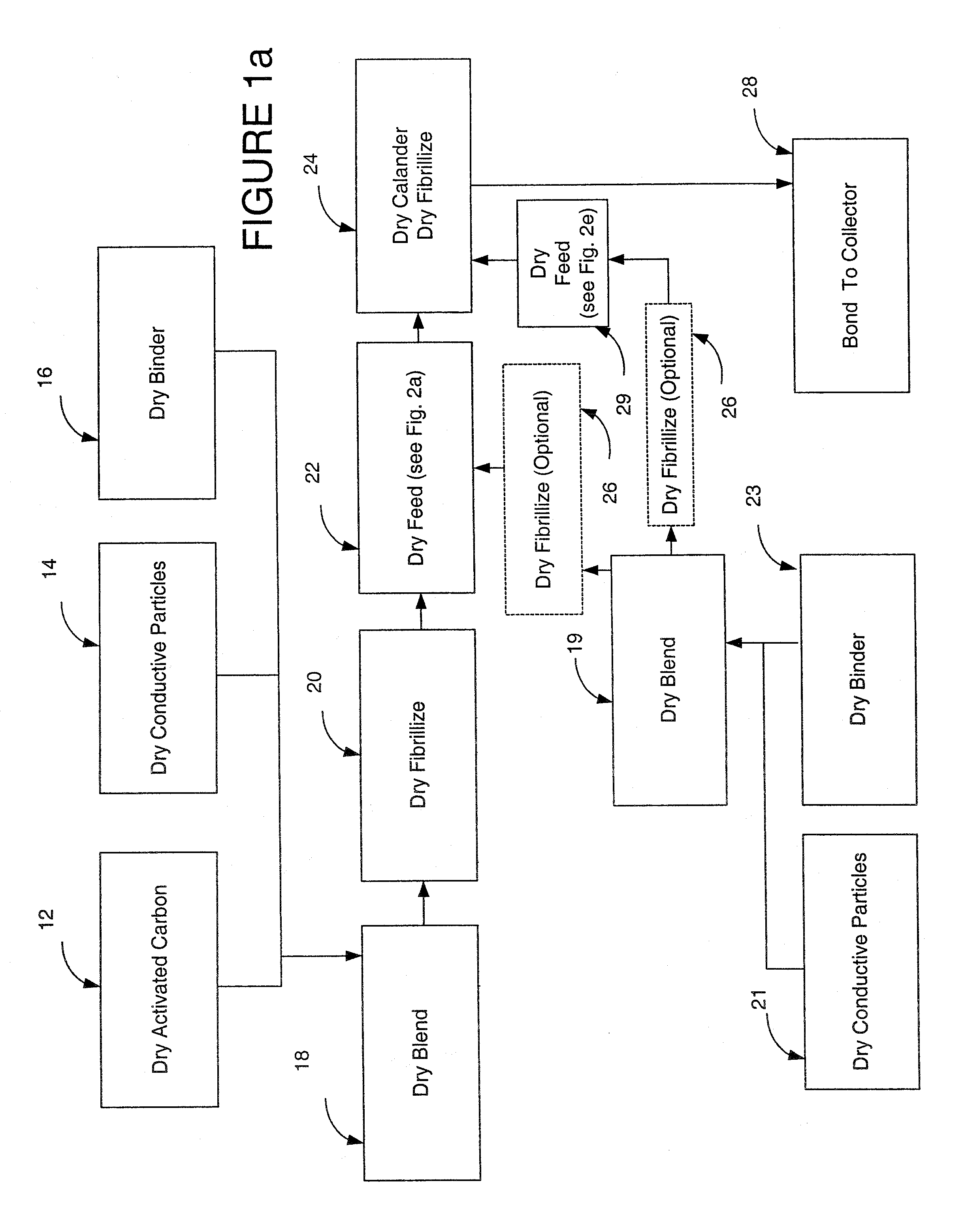
[0069]The present invention provides a high yield method for making durable, highly reliable, and inexpensive structures. The present invention eliminates or substantially reduces use of water, additives, and solvents, and eliminates or substantially reduces impurities, and associated drying steps and apparatus. The invention utilizes a dry fibrillization technique, where a matrix formed thereby is used to support a selected variety of particles. In one embodiment, the dry fibrillization technique is used to fibrillize binder. In one embodiment, the binder comprises fibrillizable fluoropolymer. In one embodiment, the fibrillizable fluoropolymer comprises PTFE or Teflon particles. In one embodiment, the matrix of dry fibrillized binder ...


PUM


Abstract

A dry process based battery that includes an electrode with one or more recycled structure is disclosed.

Description

RELATED APPLICATIONS[0001]The present application is a Continuation-In-Part of and claims priority from commonly assigned copending U.S. patent application Ser. No. 11 / 116,882, filed Apr. 27, 2005, published Nov. 10, 2005 as U.S. Patent Application Publication No. 2005-0250011, which is a Continuation-In-Part of U.S. patent application Ser. No. 10 / 817,701, filed Apr. 2, 2004, published Dec. 1, 2005 as U.S. Patent Application Publication No. 2005-0266298, which claims priority to each of U.S. Provisional Patent Application Nos. 60 / 486,002, filed Jul. 9, 2003; 60 / 486,530, filed Jul. 10, 2003; 60 / 498,210, filed Aug. 26, 2003; 60 / 498,346, filed Aug. 26, 2003; 60 / 511,273, filed Oct. 14, 2003; and 60 / 546,093, filed Feb. 19, 2004. This application is also a divisional of U.S. patent application Ser. No. 11 / 251,512, filed on Oct. 14, 2005, published Jan. 1, 2010 as U.S. Patent Application Publication No. 2010-0014215, which is a continuation-in-part of U.S. patent application Ser. No. 11 / 11...

Claims


Application Information

Patent Timeline
IPC IPC(8): H01M4/62
CPCH01M4/625H01G11/50Y02E60/50Y02E60/13H01G11/42H01M4/02H01M4/0404H01M4/0409H01M4/0416H01M4/0435H01M4/1391H01M4/1393H01M4/50H01M4/58H01M4/583H01M4/587H01M4/62H01M4/621H01M4/622H01M10/052H01M4/8668H01M4/886H01M4/8896H01M4/9083H01M4/926H01G11/38Y02E60/122H01M4/131H01M4/133H01M4/136Y02E60/10
Inventor ZHONG, LINDAMITCHELL, PORTERXI, XIAOMEI
Owner TESLA INC
Why Eureka
Try Eureka